 spudfishScott
Now that the Spikeputor CPU is complete, we turn our attention to the creation of some features to help aid in visualizing the computation, and to creating a fully functional computer via I/O components. While there are LED indicators for all of the important CPU signals, interpreting them at a glance can be challenging. To show the current data paths in a more holistic way, Electroluminescent (EL) Wire was added to the Spikeputor. Each length of wire was placed between two important nodes of the CPU. EL driver logic was added to the third pegboard, and two Sparkrfun EL Escudo Dos boards (see this website for full information, including schematics) were used to convert the logic signals into the high voltage AC required to turn on the wires.
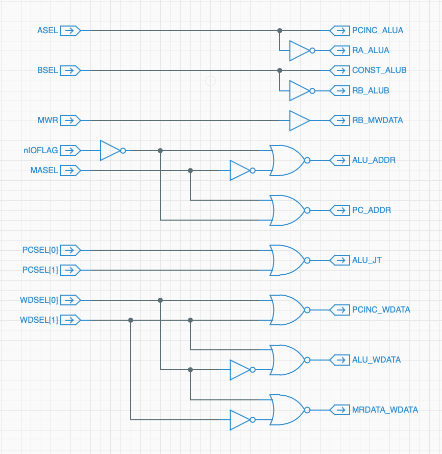
Here's a schematic of the EL Driver logic, showing the Spikeputor control signals as inputs, and the identity of the two connected nodes as outputs. For example, the ASEL signal is used to illuminate EL wire between the ALU Channel A Input and either the Register Channel A Output or the value of the PC Increment register (labeled in the schematic as RA_ALUA and PCINC_ALUA, respectively).
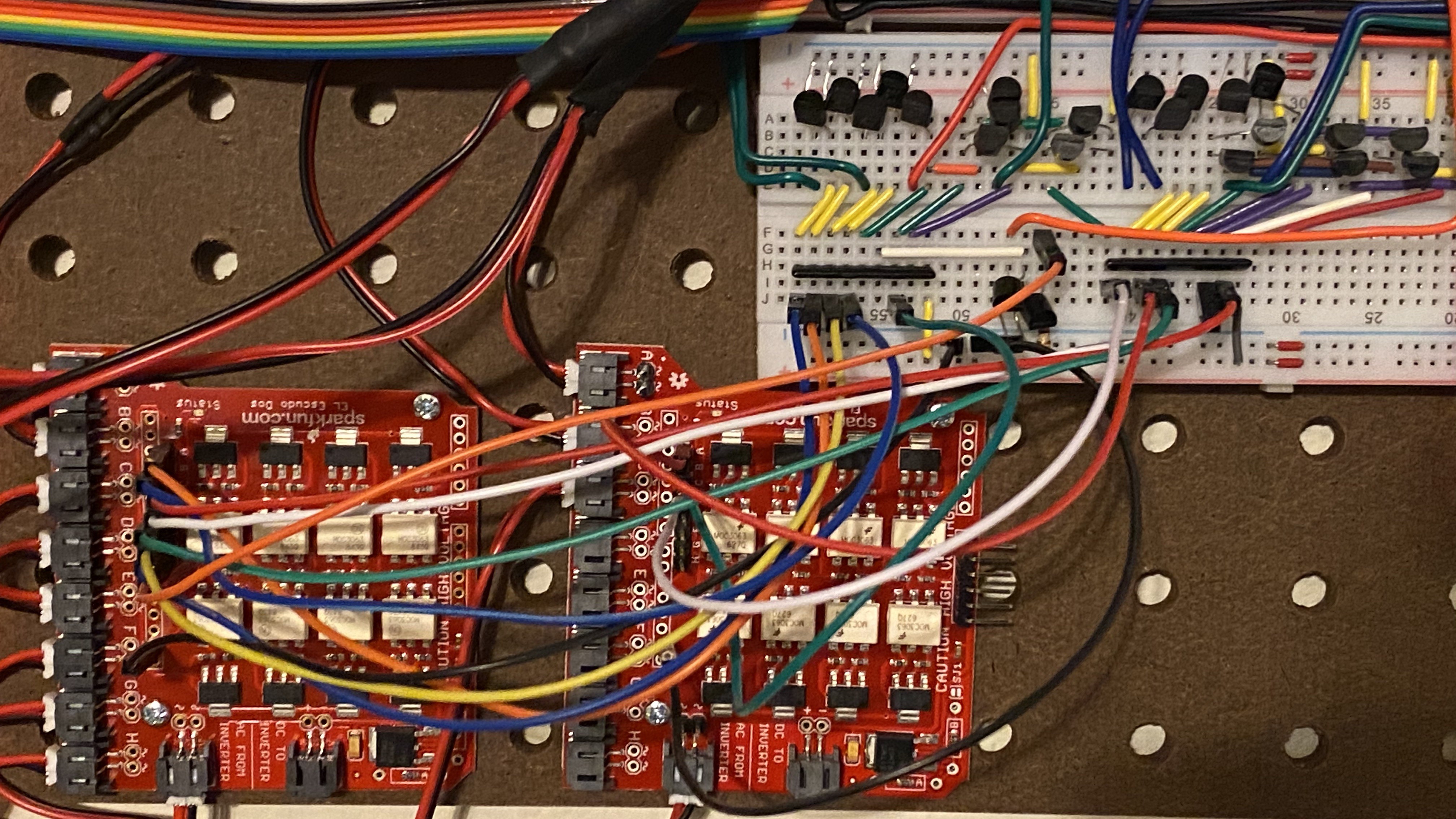
The driver logic and Escundo boards are mounted in the lower right corner of the third pegboard:
This video shows the result. The rate of the EL Wire changes can be adjusted by changing the Spikeputor clock speed, or by putting the Spikeputor CPU into single step mode.
Discussions
Become a Hackaday.io Member
Create an account to leave a comment. Already have an account? Log In.
That is absolutely mesmerizing!
Are you sure? yes | no
Agreed! It's also helpful with debugging.
Are you sure? yes | no