 spudfishScott
Until now, I've been generating clock signals via an Arduino. With the Register Memory and ALU boards complete, and work beginning on Control Logic, it was time to think about building a clock for the Spikeputor. Like many other homebrew computers, I wanted the clock rate to be variable based on user control of some kind of knob or slider. I also wanted the ability to switch to a mode where the user can control the clock pulses on a step-by-step basis for a fine-grained look at the CPU in action.
Because everyone loves a 555, I decided that it would be an appropriate timekeeper for the Spikeputor. I considered creating a discrete version (see this great kit, for example), but since space on the pegboards was filling up fast, I decided to start with ICs, and then go discrete later on if space is available.
Here's the schematic for the clock circuit:
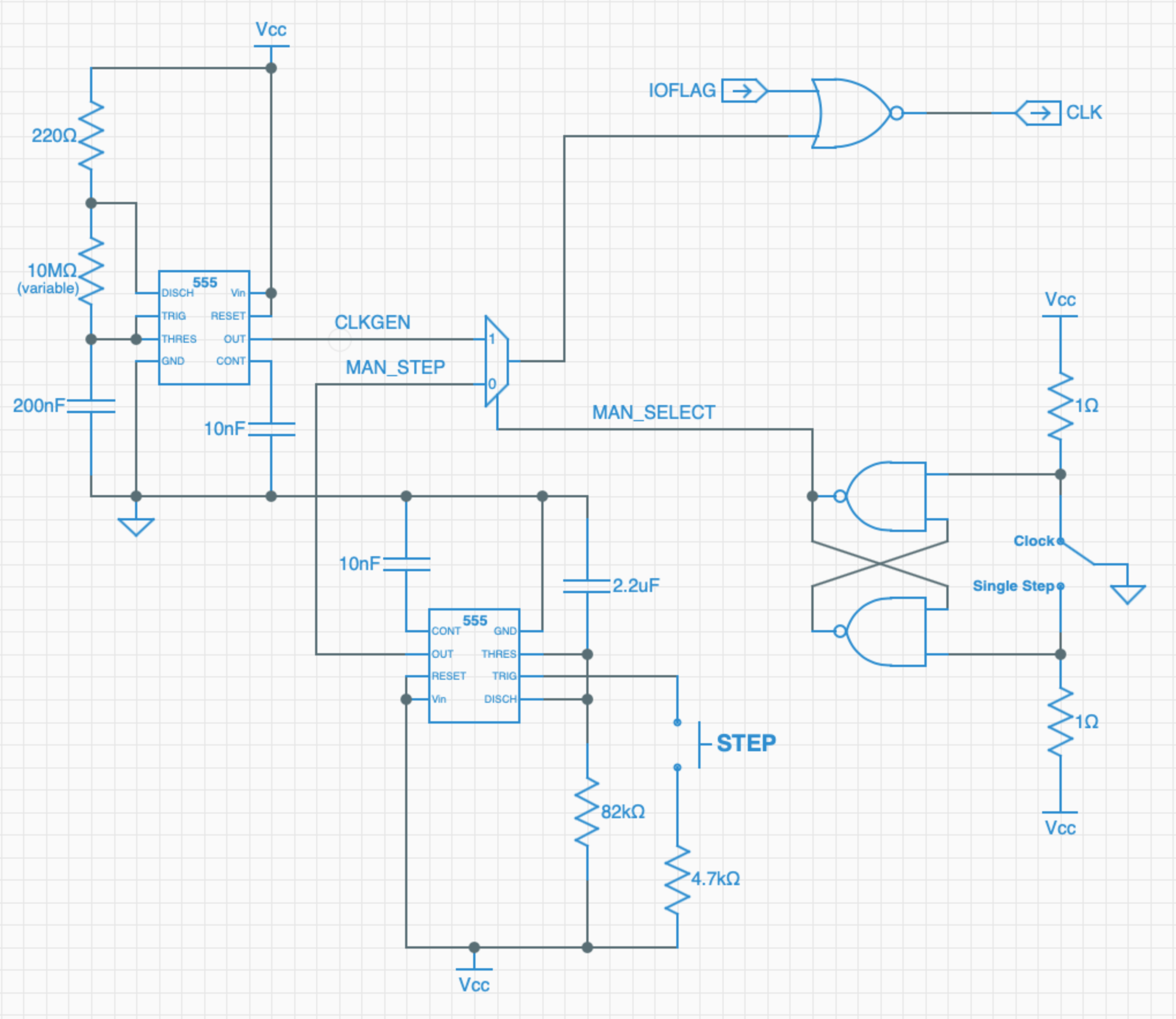
I'm actually using two 555's - one to generate the variable-rate clock signal, and another to generate a clean 200 ms debounced pulse for the manual step pushbutton. Using a 10 MΩ variable resistor and a 200 nF capacitor, clock rates between 0.35 and about 17,000 Hz are possible. I might want a little more dynamic range, so I'm considering switching to a control knob where I can substitute a larger range of resistors, but for now, the 10 MΩ slider will do.
The 555 clock signal and the single step pulses go into a 2-channel MUX, the output of which is controlled by a Clock/Step Select switch, itself debounced via an SR latch. Finally, one final gate allows for setting IOFLAG high to stop the clock so the DMA I/O can occur.
Here's how it all fits together on a board:
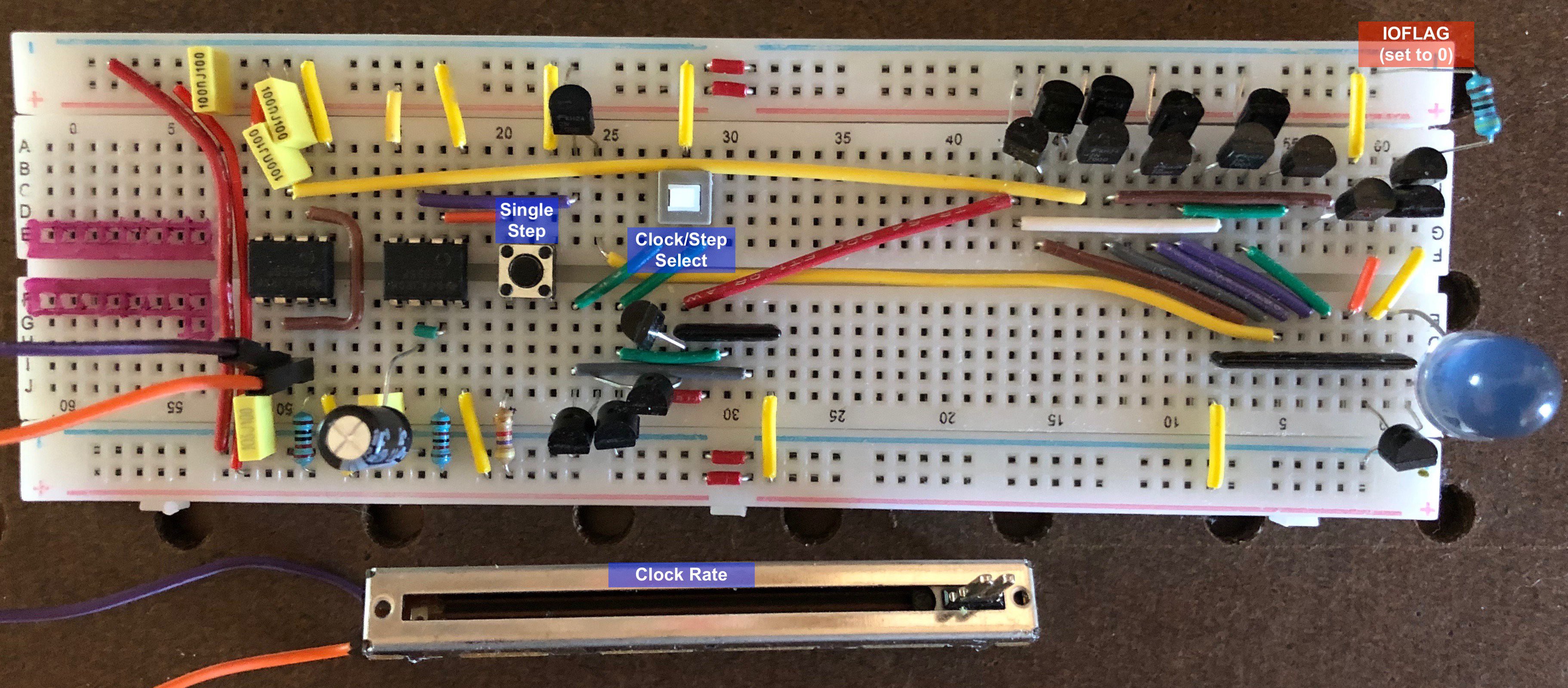
IOFLAG is hard-wired to 0 right now, but that will eventually connect up to the BIAS board of the Apple II for I/O.
And here's a little demo of the board in action. We start in clock mode, adjust the rate, then switch over to single-step mode, step a bit, then switch back to the clock. This board drives the proto-Spikeputor perfectly!
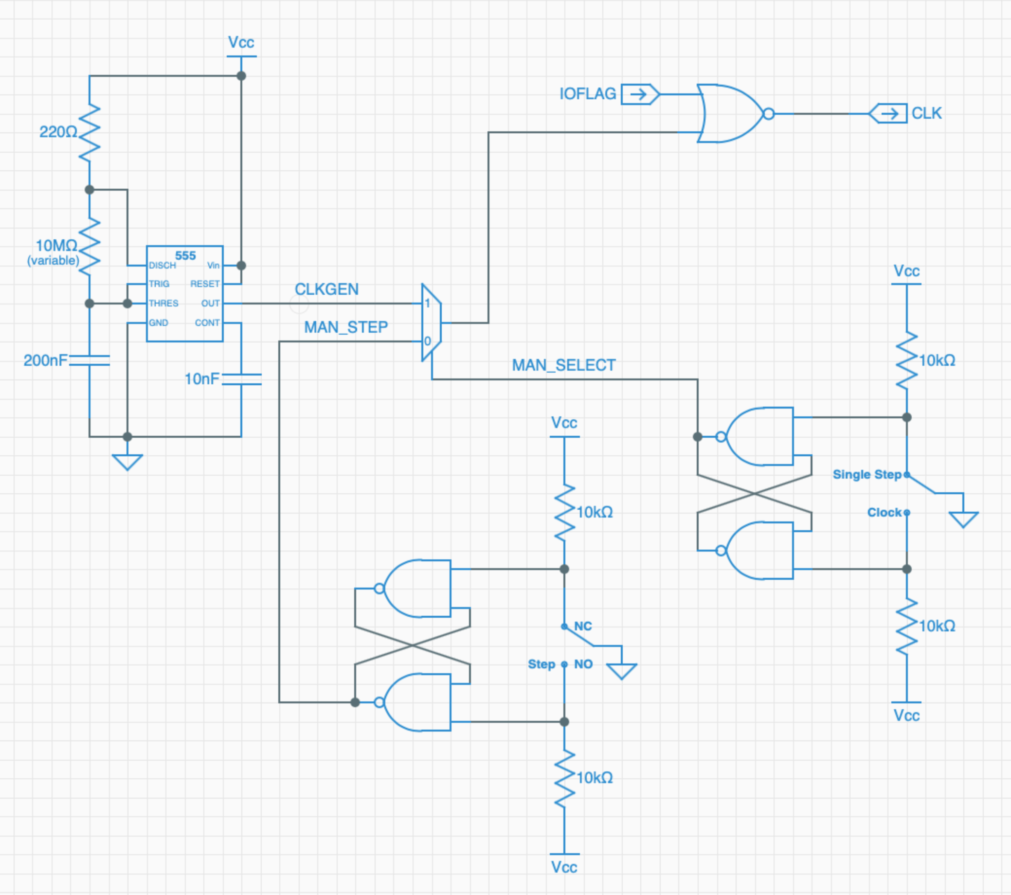
UPDATE: I decided to eschew one of the 555 chips in anticipation of eventually replacing the single remaining 555 with discrete components. Instead, I used a DPST momentary pushbutton switch for the single step pulse, debounced via another SR Latch as shown here:
Discussions
Become a Hackaday.io Member
Create an account to leave a comment. Already have an account? Log In.