 spudfishScott
The final two components of the third Spikeputor pegboard, and the last two pieces of the main Spikeputor design, are the electroluminescent (EL) wire driver and sixteen bits of discrete general purpose output memory. The EL wire driver is just a small set of simple logic gates to convert control signals to individual wire output signals – more on that later when all of the EL wire has been mounted. The GPO memory was made based on the design for the discrete static "screen" memory that will be realized on the fourth and final pegboard. The memory design features five transistors, four resistors, and an LED per bit:
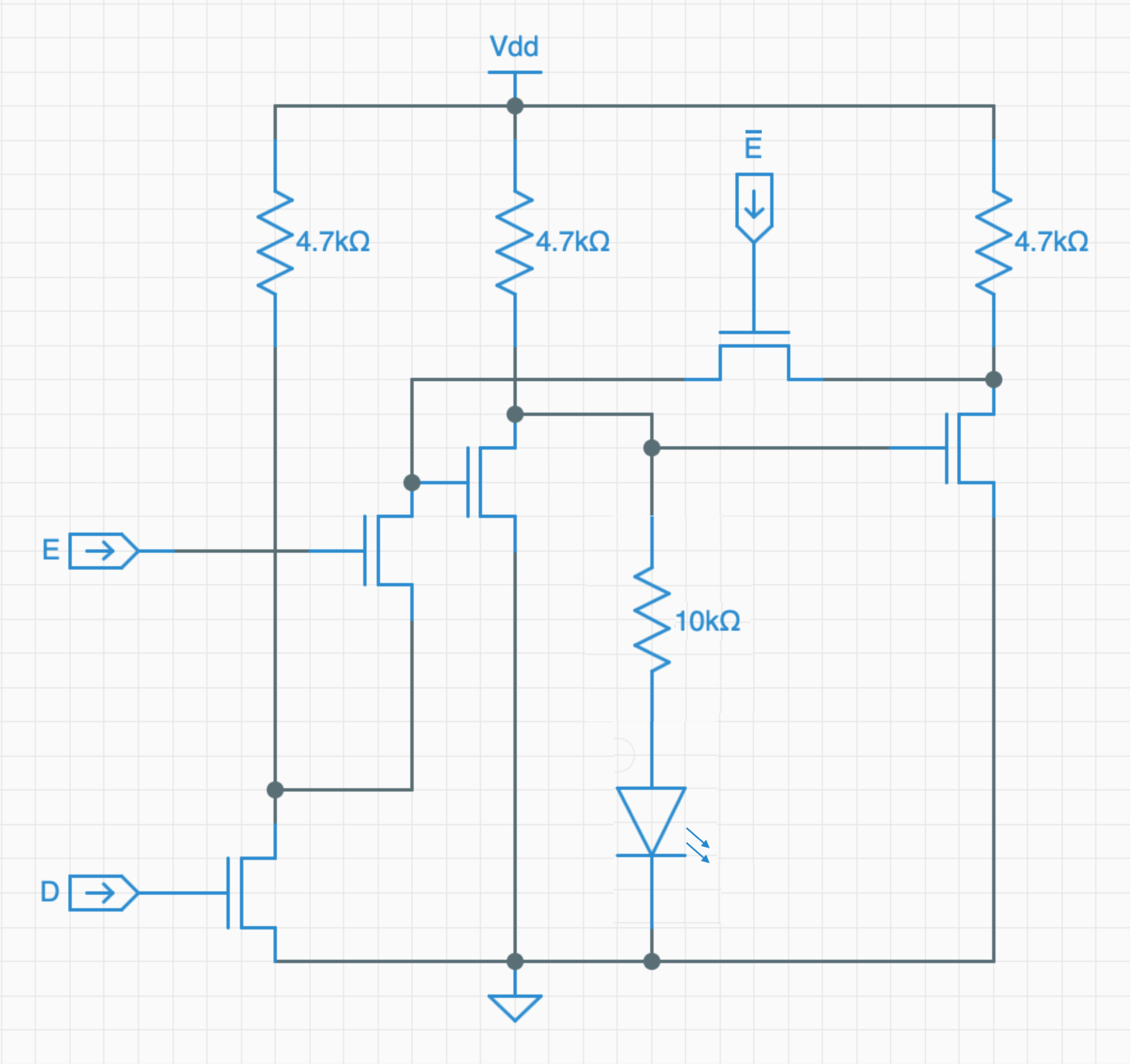
The memory bit is set or cleared by placing the desired value on D, asserting E, and clearing ~E. While the screen memory design is "write-only", the value of the bit can be accessed by buffering the signal off the drain of the transistor on the far right. This is how the general purpose output lines are implemented:
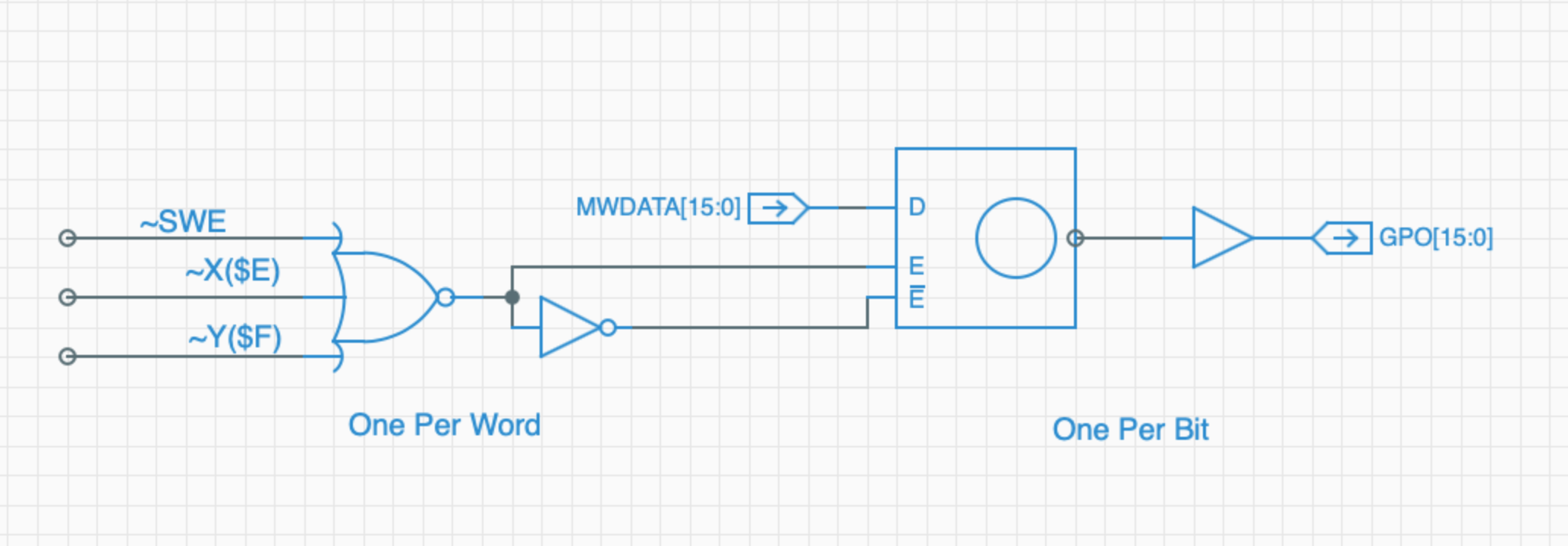
The data lines are pulled directly from the Spikeputor MWDATA bus. E and ~E are set by NORing the appropriate active-low decoded address lines. Writing to any address $7Fxx sets ~SWE low, while the low byte of the address is decoded into twelve Y signals for the high nybbles ($0-9, plus $A and $F) and eight X signals for the low nybbles (only even numbers). So, to write to the GPO, simply store the desired value in memory location $7FFE. Putting it all together, it looks like this:
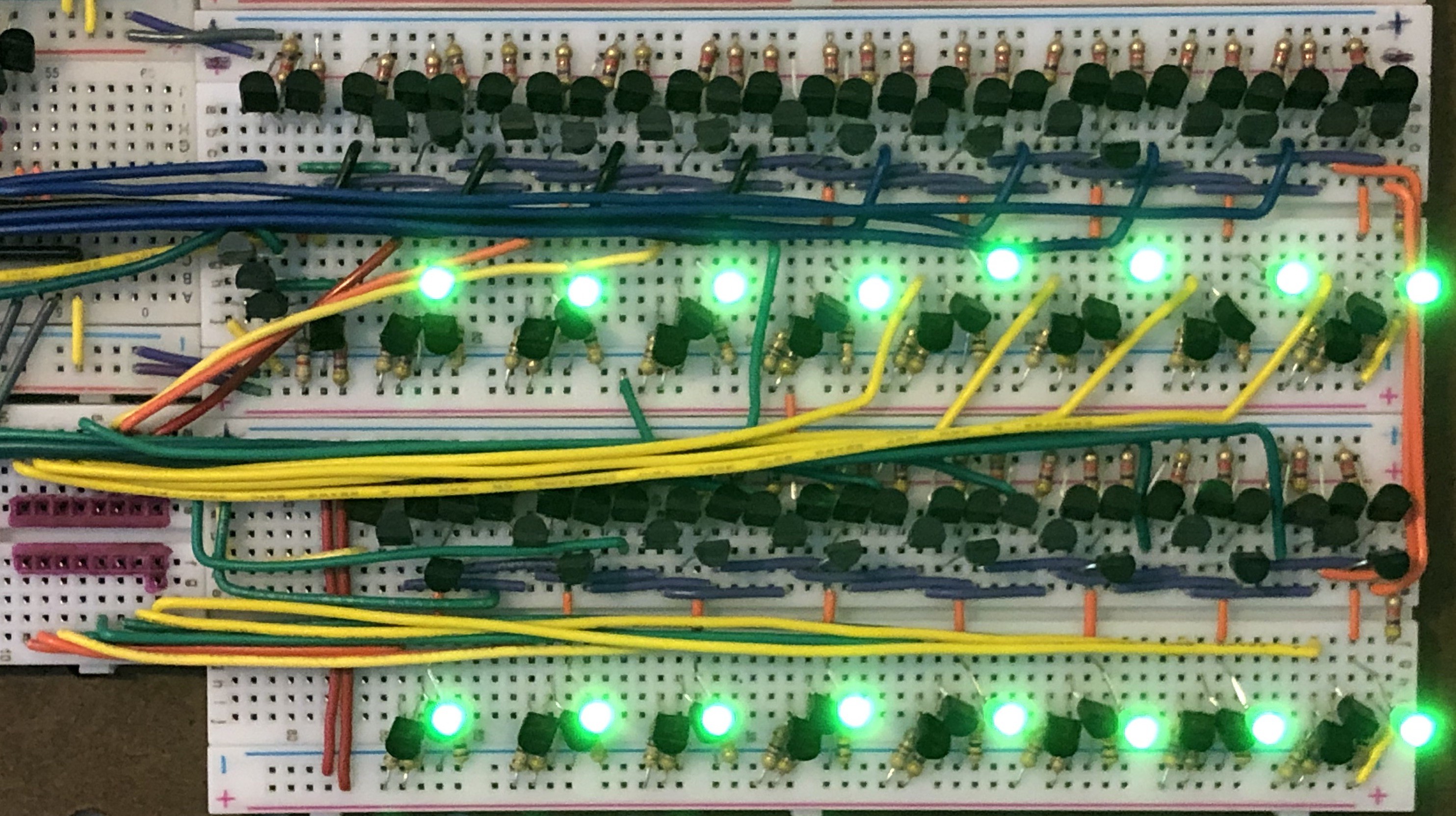
The red outline on the lower left indicates where a 16-pin DIP cable can be plugged in to access the output signals. The LEDs reflect the values of each bit. Here's a video that shows a program running that cycles values through the GPO address:
Now that the third pegboard has been completed, it was mounted on the wall, and the cables running between the Spikeputor modules was cleaned up mounted clips. Here's the big picture:
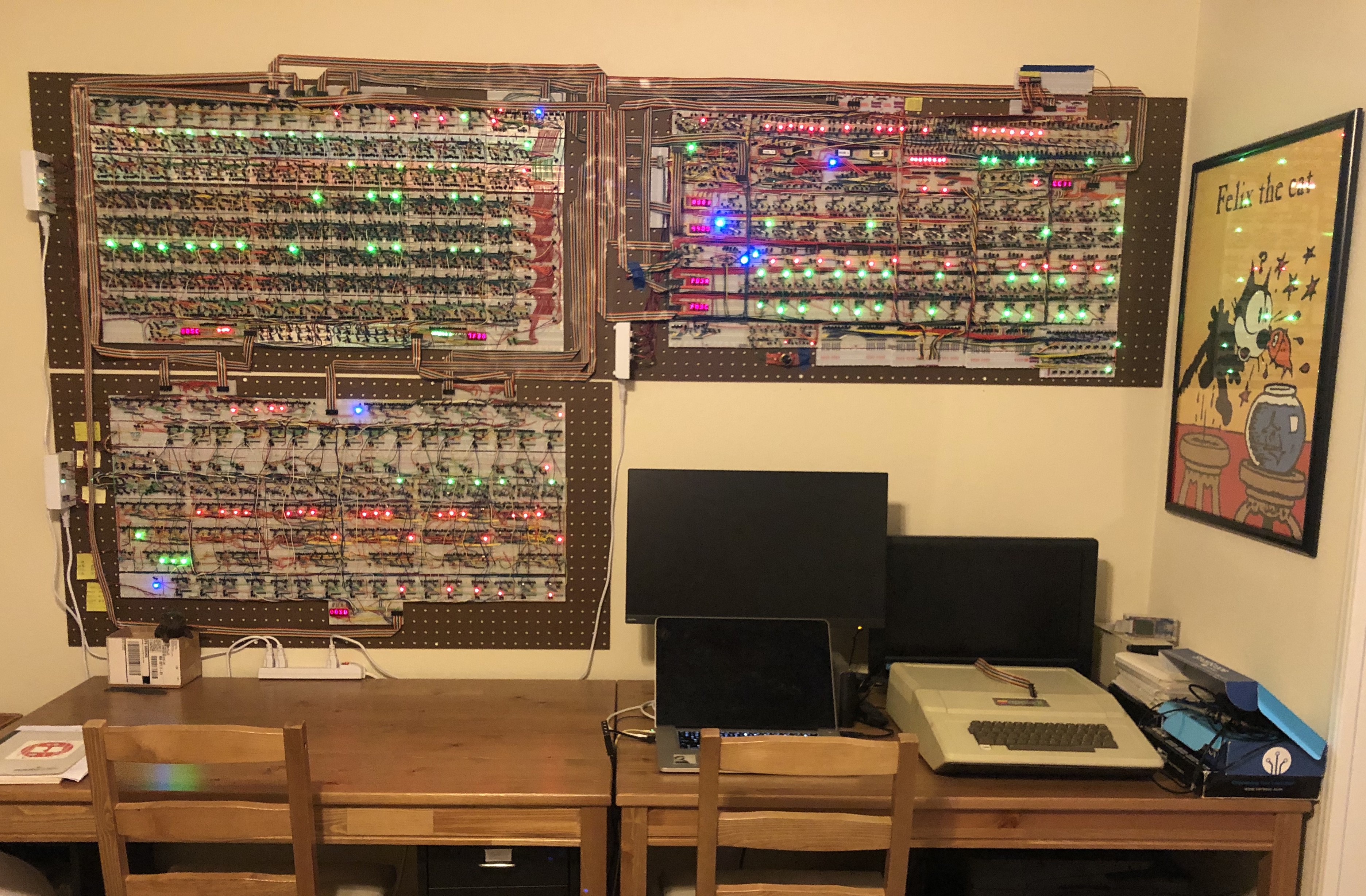
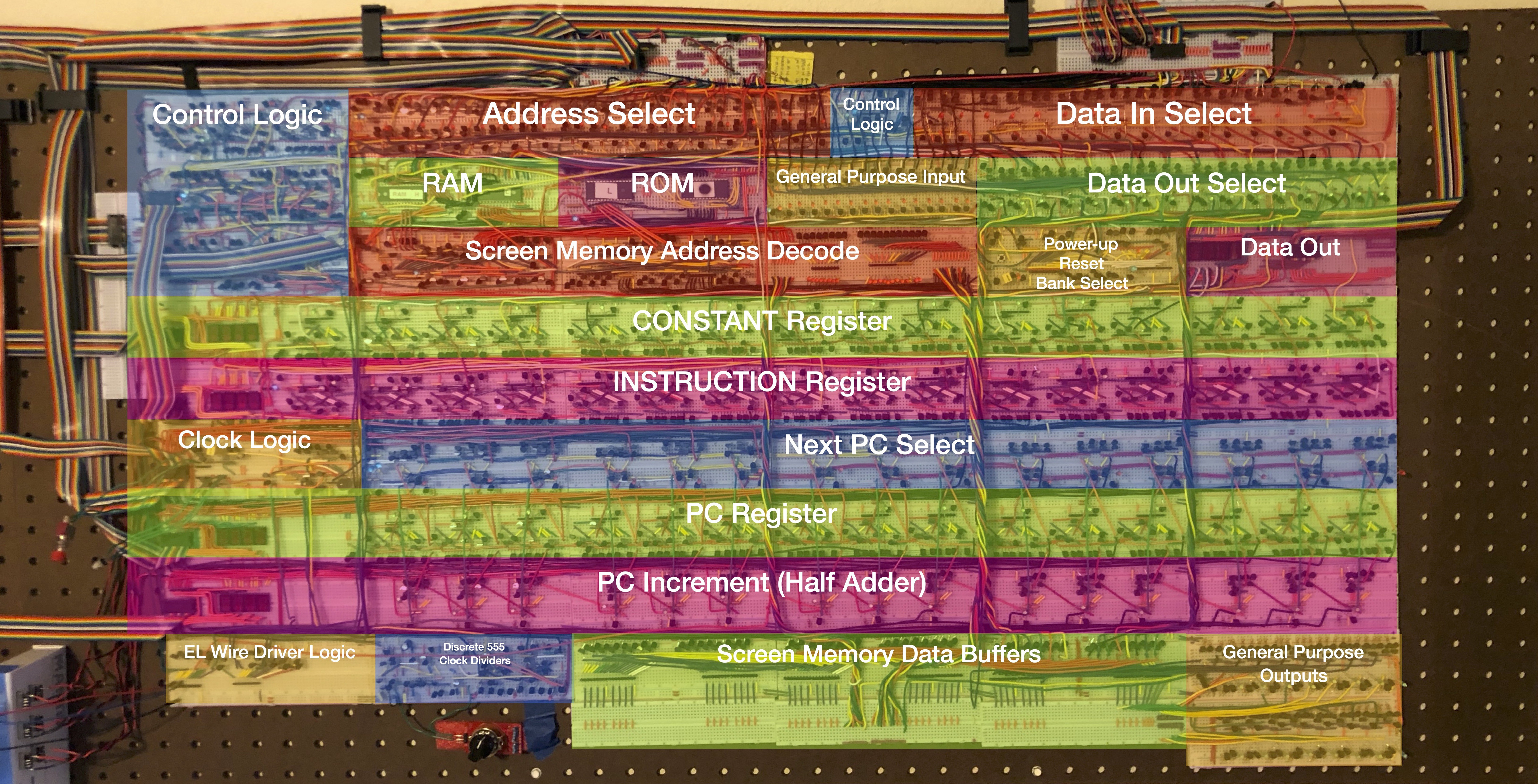
Here's a close-up of the third pegboard with a summary of all of the modules it contains. The previous two pegboards are documented in the sections on the ALU and Register Memory.
Discussions
Become a Hackaday.io Member
Create an account to leave a comment. Already have an account? Log In.