 spudfishScott
To determine the current command that the Spikeputor is running, one can look at the INSTRUCTION and CONSTANT registers and work through the bits according to the Spikeputor ISA (described here), but that's a pretty complicated thing to do in one's head and doesn't lend itself to rapid debugging. To promote further understanding of what's going on, we can install a microcontroller-based interpreter which polls the appropriate fetch register and a few key control signals, translates the data into a human-readable assembly language command, and displays the command on a simple alphanumeric display.
All of this was accomplished using an Arduino Duemilanove board and a serial enabled 16x2 LCD display from SparkFun (link here). The inputs were drawn from the 16-bit CONSTANT register. This register is updated with the value of the memory output data bus on each tick of the clock. By including as inputs the CLK signal and the ISEL signal (which goes high at the beginning of each command cycle), the microcontoller can determine when the CONSTANT register is valid for the opcode, and, by examining the opcode, whether or not it would need to look again at the register on the next clock cycle to get the second word of two-word Spikeputor commands.
The microcontroller C code is in the File section (link here).
Here's a screen shot of the completed display/microcontroller setup, positioned close to the output of the CONSTANT register.
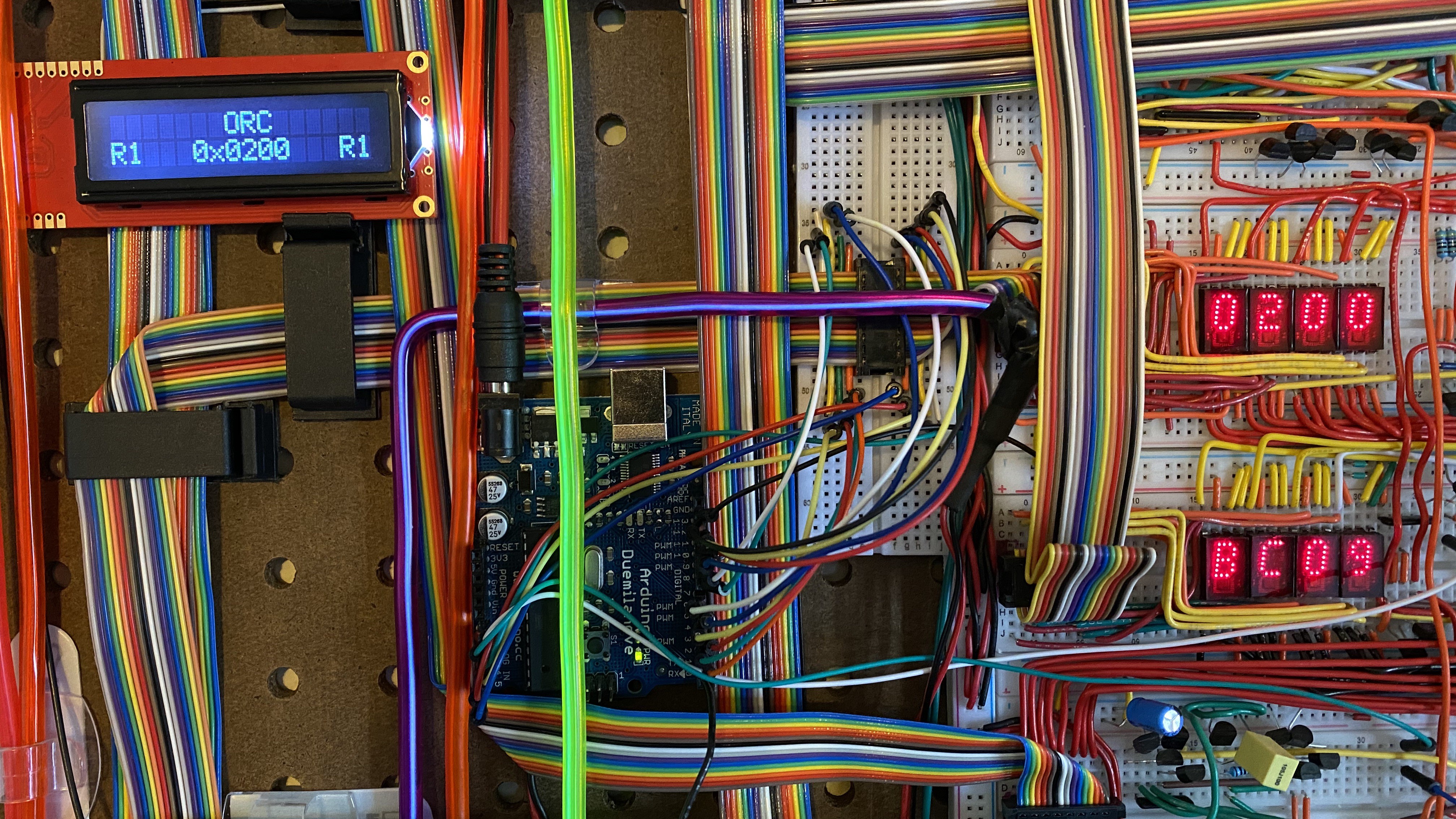
At the time this image was taken, the first word of the two word command was first stored in both CONSTANT and INSTRUCTION registers. The microcontroller pulled the value (0xBC09) from CONSTANT, check bit 10, found it was set, and thus waited for the next clock pulse. At that time, the second word of the command (0x0200) was stored in the CONSTANT register (INSTRUCTION is only updated after CPU phase 0). The microcontroller then read this second value, computed the output, and wrote the entire command, ORC(R1, 0x0200, R1), to the display via the microcontroller's serial output.
Here's a video of several Spikeputor commands passing through the interpreter:
Discussions
Become a Hackaday.io Member
Create an account to leave a comment. Already have an account? Log In.