 spudfishScott
Now that the CPU is complete, it was time to design methods for the Spikeputor to communicate with the outside world. First up, taking advantage of the DMA interface described in the Memory log entry and using it to upload programs to the Spikeputor and to establish two-way communication protocols. As mentioned in the project description, an old Apple ][ Plus was chosen as the primary I/O device for extra retroputing flair. To implement this functionality, two PCBs were designed and fabricated. First, a generic SPI Controller card was made to plug into an Apple ][ peripheral slot. That project is described here: SPI Controller Card for the Apple ][.
To convert raw SPI commands to operations that can halt, reset or interrupt the Spikeputor, transfer data to and from the Spikeputor, and poll important Spikeputor signals (CLK and ISEL), an SPI peripheral board was designed. The board has five connectors. One connector goes to an SPI Controller card with the standard SPI signals (~CS, SCK, COPI, CIPO). The other four connect to 1. the Spikeputor control signals (comprised of four outputs: ~IOFLAG, IO_WE, RESET, and IRQ, and two inputs: CLK and ISEL), 2. the Spikeputor address bus, 3. the Spikeputor data out bus, and 4. the Spikeputor data in bus. Address and data connectors are 16 bits wide, so the Spikeputor DMA module can be controlled directly by this card. The card can respond to one-byte commands or three-byte commands as described below. Each command transaction starts when the SPI channel is set low and is completed when the SPI channel is set high. To allow for the slow Spikeputor address and data buses to stabilize, wait at least 40 µs after starting the SPI transaction before sending and receiving bytes, and wait at least 60 µs after the end of the SPI transaction before starting a new transaction. Bits are latched into the card's shift registers on the rising edge of the SCK pulse. Clock speed is set from the Controller card of the Apple ][ and this board works well with the on-board clock signal (2 MHz).
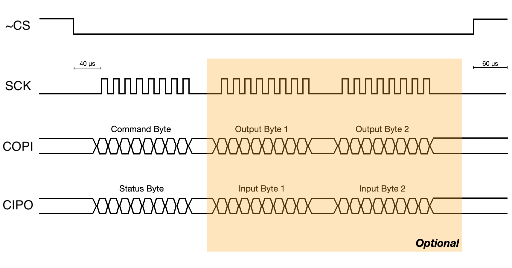
The board responds to eight commands. The command is in the high nybble of the first byte sent. The low nybble is ignored. Three bytes are buffered on the card, so for single byte commands, two extra bytes and be sent and received with no ill effects. Commands are executed at the end of the SPI transaction (when ~CS is asserted). The command set is as follows:
- Command 0xF0: HALT (one-byte command) - Waits until the Spikeputor ISEL signal is high (beginning of CPU Phase 0) and clears the ~IOFLAG signal, which halts the Spikeputor and sets the Address and Data Out selectors to the BIAS lines.
- Command 0xE0: RESTART (one-byte command) - Restarts the Spikeputor immediately by asserting the ~IOFLAG signal. This restarts the Spikeputor clock where it was stopped, at the beginning of CPU Phase 0, and returns control of the data and address busses to the Spikeputor CPU.
- Command 0xD0: IRQ (one-byte command) - Waits until the Spikeputor ISEL signal is high (beginning of CPU Phase 0) and asserts the Spikeputor IRQ signal until the ISEL signal transitions from low to high again. The is required for the Spikeputor to successfully execute an interrupt request.
- Command 0xC0: RESET (one-byte command) - Waits until the Spikeputor CLK signal is high and asserts the Spikeputor RESET signal until the next clock pulse, insuring the completion of the Spikeputor RESET cycle regardless of Spikeputor clock speed.
- Command 0xB0: AUTO INCREMENT (one-byte command) - After this command is executed, the current Spikeputor Address Bus will be auto-incremented after each subsequent READ or WRITE command. Useful for sending multiple words to or from the Spikeputor.
- Command 0xA0: SET ADDRESS (three-byte command) - After this command is executed, the current Spikeputor Address Bus will be set to the value of the word specified by Output Bytes 1 and 2 (big-endian) starting with the next command. AUTO INCREMENT is disabled after this command. The address bus stays the same unless a new SET ADDRESS command is issued or AUTO INCREMENT is re-enabled.
- Command 0x90: WRITE (three-byte command) - After this command is executed, the value of the word specified by Output Bytes 1 and 2 (big-endian) is written to the current Spikeputor address bus location. If AUTO INCREMENT is set, that address is incremented before the write takes place.
- Command 0x80: READ (one-byte write, three-byte read command) - This is a dummy command that does nothing but set the Spikeputor Address Bus to the next value (if AUTO INCREMENT is enabled). Since the Input Bytes 1 and 2 always reflect the status of the Spikeputor Memory Data Output bus, they can be read to get the value of memory at the current address.
The status byte emitted during each SPI transaction can be interpreted as follows:
- Bit 7 - Current value of ~IOFLAG output
- Bit 6 - Current value of IRQ output
- Bit 5 - Current value of RESET output
- Bit 4 - Set if AUTO INCREMENT mode is active
- Bit 3 - Current value of Spikeputor ISEL signal
- Bit 2 - Current value of Spikeputor CLK signal
- Bit 1 - Bit 2 of current Address Bus output
- Bit 0 - Bit 1 of current Address Bus output
The Input Bytes 1 and 2 emitted during each SPI transaction always reflect the current state of the Spikeputor Memory Data Output.
All output signals can be read at any time through the READ command, even if the Spikeputor is not halted. This might be useful to debug signals and current memory data. IRQ and RESET commands also work, but WRITE and SET ADDRESS commands will not work unless the Spikeputor has previously been halted as that is the only way to transfer control of the Address and Data buses to the BIAS card.
The full schematic and KiCAD project files are in the Files section.
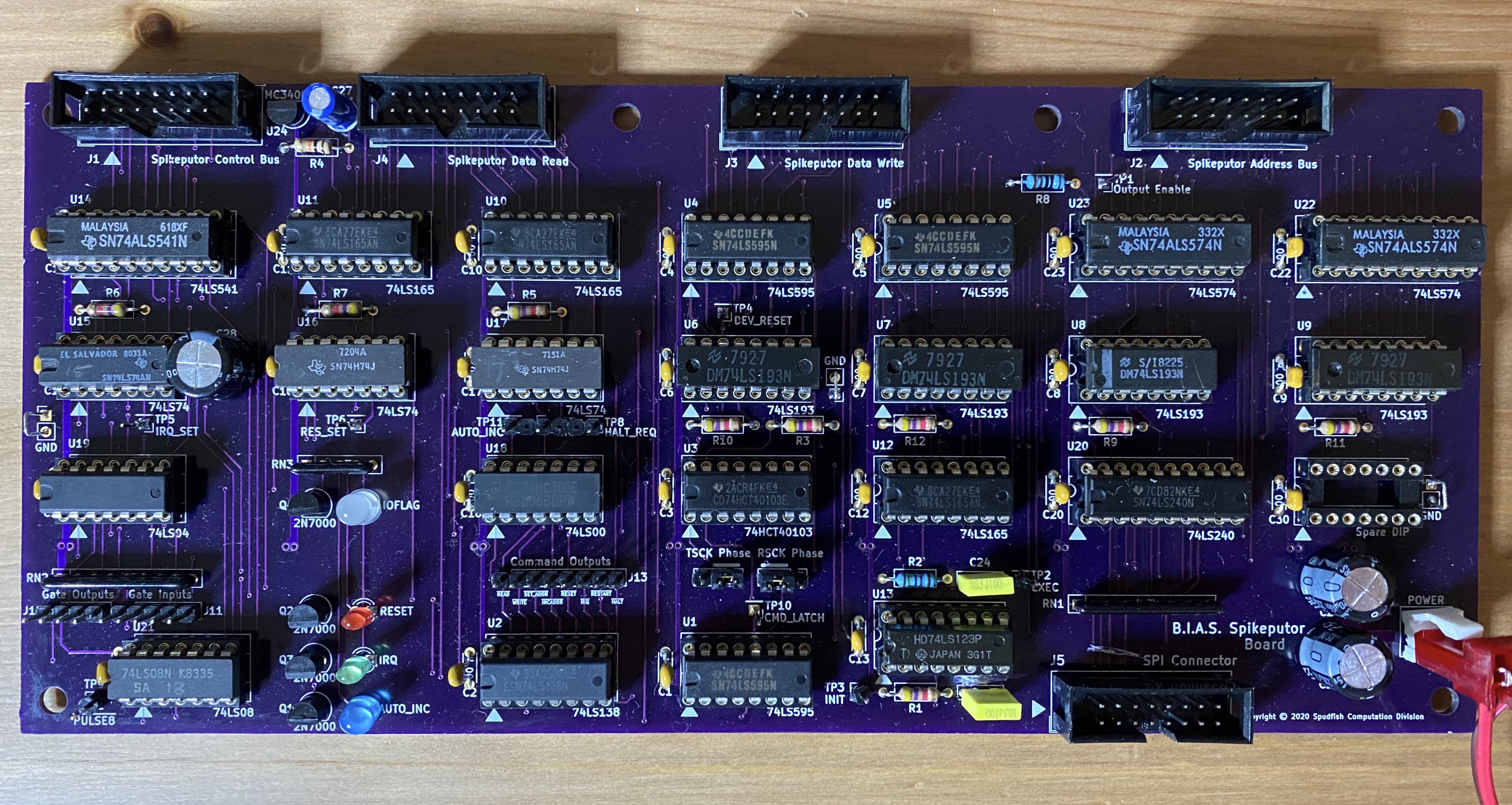
Here's a picture of the completed peripheral board:
Once the BIAS hardware was complete, a program was written on the Apple ][ to upload machine code to the Spikeputor and execute it. A shared input and output buffer mechanism was implemented in software using Spikeputor memory that can be monitored by the Apple using the BIAS hardware. By using this shared buffer system, the Apple ][ can be used as a simple teletype. By defining some control character sequences to send graphics commands, the Spikeputor can ask the Apple to display text or hi-res or lo-res graphics lines and points. This video shows a demonstration of basic input and output text by displaying prompt strings, accepting input, and reacting to that input with more text and graphics. Although the Apple is handling all Input/Output, the Spikeputor is completely running the show. On the Spikeputor side, this involved writing a suite of low level commands to do multiplication and division, random number generation, string handling, and sending and receiving text output and input through the shared buffers. These routines will eventually be incorporated into the Spikeputor ROM.
Discussions
Become a Hackaday.io Member
Create an account to leave a comment. Already have an account? Log In.