 spudfishScott
Using the Spikeputor's general purpose input and output feature, it was easy to directly connect a keyboard and two vacuum fluorescent displays, augmenting the BIAS-related I/O described in the previous log entry and providing true stand-alone I/O. Due to the low speeds of the Spikeputor, a parallel approach was taken for both input and output devices. There aren't many parallel keyboards available, but there are several keyboard adapters that will convert standard PS2 or USB keyboards to a parallel signal, mainly for retroputing use. Thus, a PS2 keyboard adapter for the Apple ][ (see this link) was hooked directly to the Spikeputor's general purpose input (GPI) bits 15 through 8. A small amount of hardware logic was added so the Spikeputor could track when a new key is pressed, taking advantage of the same hardware system that the Apple ][ used. The high bit of the GPI is connected to the output of an S-R flip-flop. The SET input of the flip-flop is connected to the STROBE output of the keyboard, and the RESET input is connected to a single bit (bit 10, in this case)of the Spikeputor's general purpose output. To read the keybaord, first reset the flip-flop by clearing and resetting bit 10 of the memory address mapped to the GPO. Then, read the top eight bits of the GPI until the STROBE bit goes high (a key has been pressed). Clear the strobe as before to get ready to read the next keypress and report the ascii value of the keypress. The Spikeputor code for reading from the keyboard is shown here. Recall from the Memory discussion that GPO and GPI are special memory locations $7FFC and $7FFE, respectively, and STRB_MASK is 0b0000010000000000.

Two Noritake VFDs were used as displays. One is a 2 x 40 character display which accepts ascii input for characters and commands. The other is a 128 x 64 pixel display. Both have parallel interfaces for quick data transfer, eliminating the need for excess computation on the Spikeputor side. Each display works by clearing a ~CS input, setting the data bits of the parallel interface, and then pulsing a ~WRITE input to latch in the new information. In the case of the graphics display, there is also a C/~D (Command/~Data) input signal, which needs to be set depending on whether the input is pixel data or a command to change the position or set other display parameters. All of these signals derive directly from the Spikeputor GPO as shown in the following schematic (which also includes the keyboard input logic):
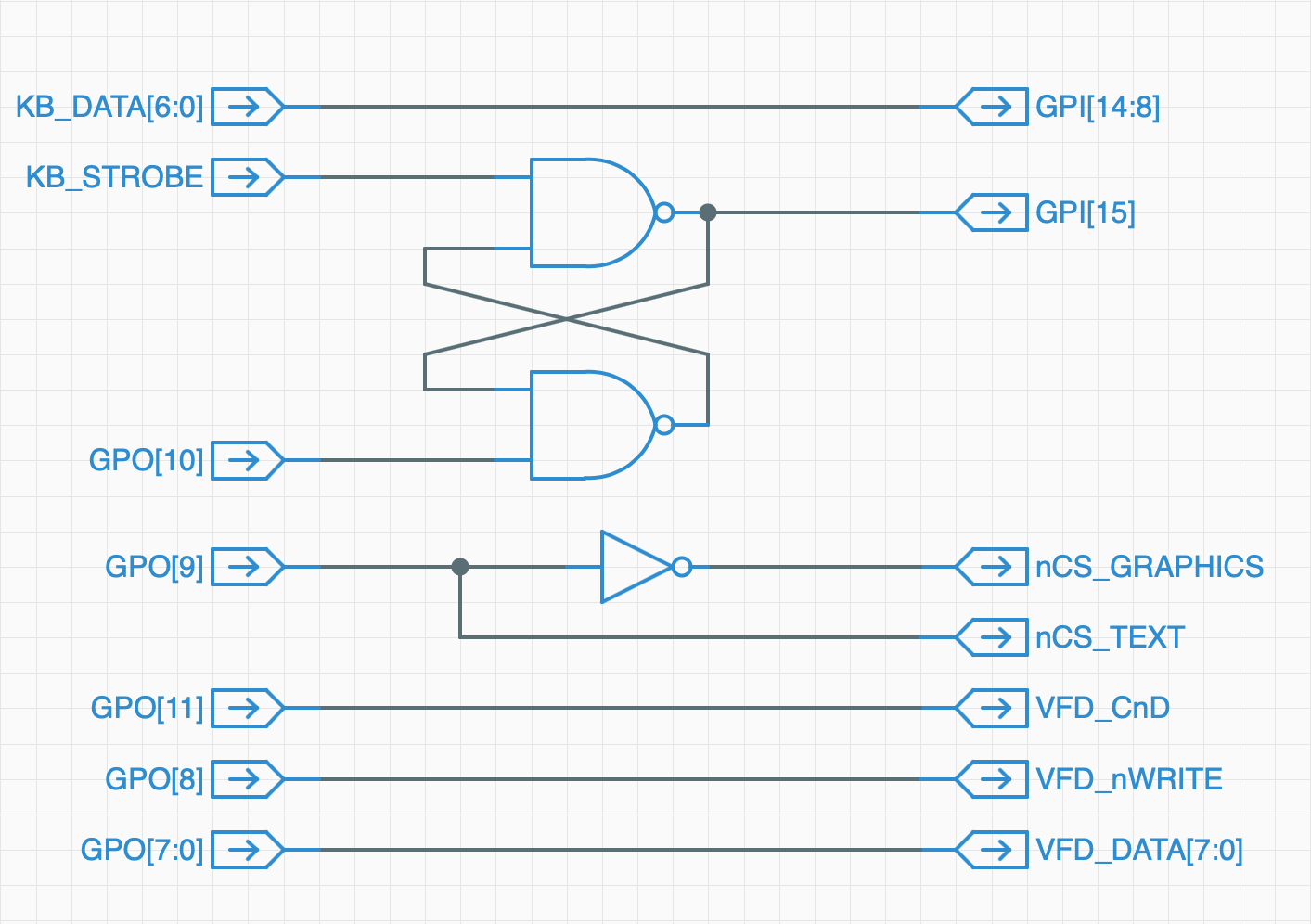
Note that bit 9 of the GPO serves as a Text/Graphics output switch so they can share all of the other signals coming from the Spikeputor.
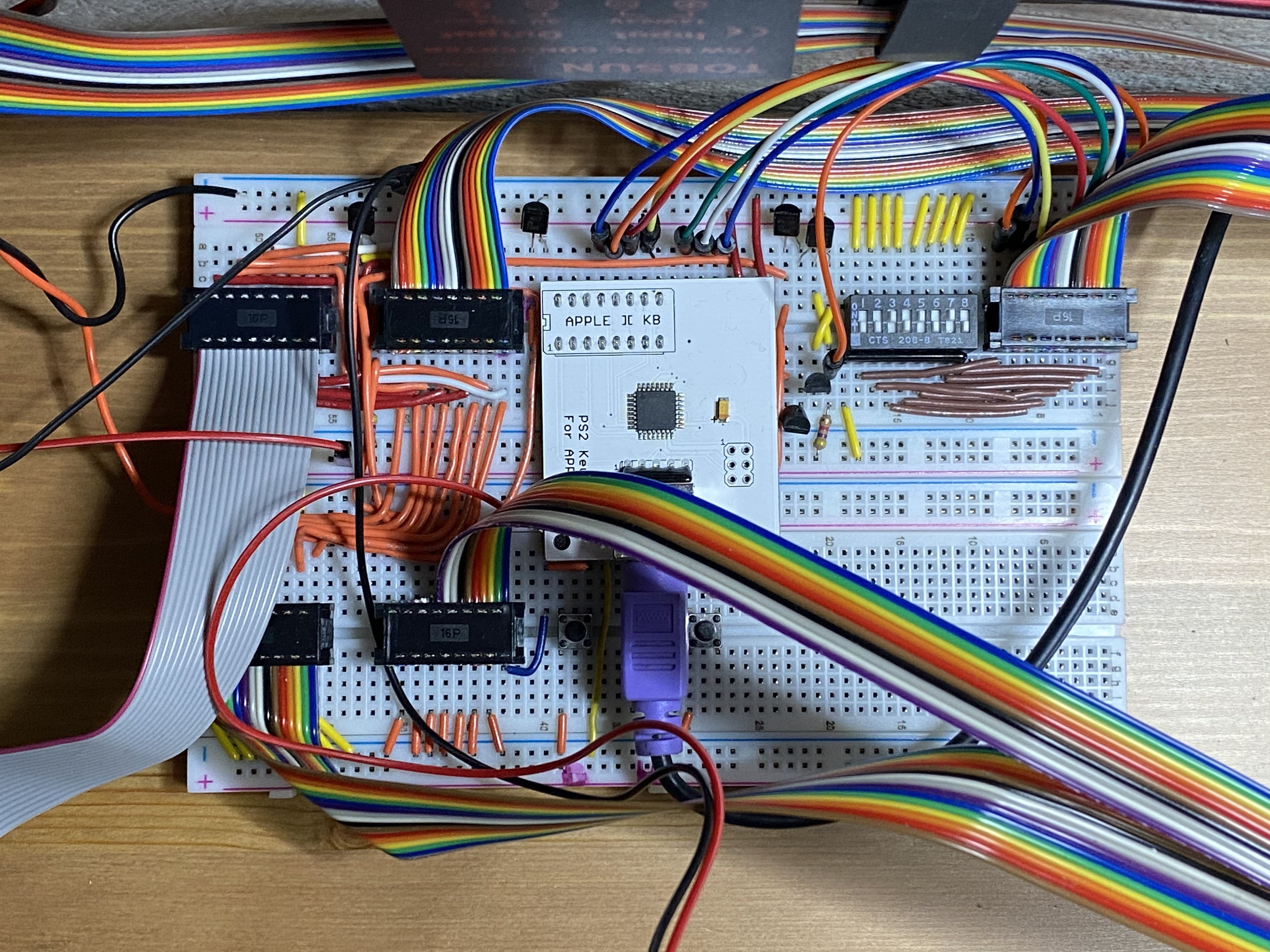
The actual I/O board is shown below. The general purpose input line is in the upper right. the DIP switches set bits 0-7 of ther Spiekputor and are reserved for future inputs. The PS2 to Apple ][ Parallel adapter is in the center, just to the left of the flip-flop circuitry (four transistors). The General Purpose Output line from the Spikeputor is immediately to the left of that on the top. The two cables on the bottom go to the graphics display and the gray cable on the upper left goes to the text display.
Here's a demo of both text and graphics output and keyboard input. The demo is running at full speed (3.3 kHz), showing that even simple graphics commands such as line drawing are currently quite slow, but definitely workable!
The Spikeputor is now a full-function computer! Further refinements will be a load/save capability through the BIAS/Apple ][ system, a ROM image, including important BIOS routines as well as a functional monitor, a pegboard of hand-made memory, and some additional inputs and outputs.
Discussions
Become a Hackaday.io Member
Create an account to leave a comment. Already have an account? Log In.