 davedarko
http://rayshobby.net/a-mosfet-based-fix-to-the-makerbot-extruder-motor-problem/
attiny85
FDC6333C -2(.5) A 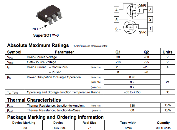
 http://www.bristolwatch.com/ele/h_bridge.htm
http://rayshobby.net/a-mosfet-based-fix-to-the-makerbot-extruder-motor-problem/
attiny85
FDC6333C -2(.5) A http://www.bristolwatch.com/ele/h_bridge.htm
Discussions
Become a Hackaday.io Member
Create an account to leave a comment. Already have an account? Log In.
👌👌👌👌👌👍🏻👍🏻🤙🤙🤙🤙
Are you sure? yes | no
I'm restricting the voltage of everything to a single voltage of 4.2V to 3.2V for this ;) read: attiny and motor have the same source because reasons - it's for RC- models running on 1cell LiPos.
"Haha, I think, if he hadn't already ordered the boards, we might've succeeded in scaring daveDarko away from this project..." - @esot.eric
:) you're right about that one! I'm not that worried about shorting because of the integrated mosfet H-bridges I've seen and I've basically just copied that with 2 np-channel thingies.
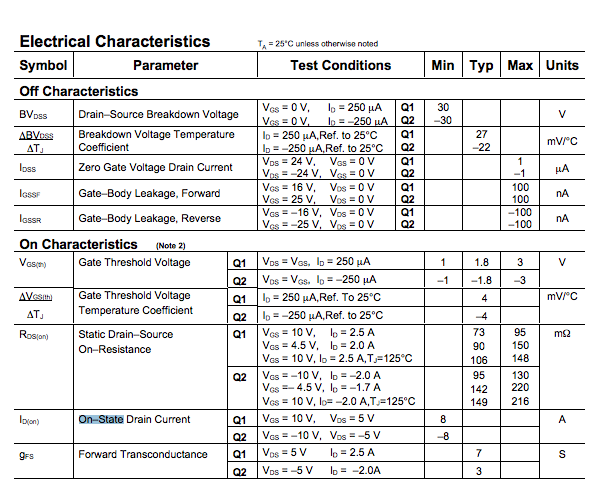
The Gate Threshold voltage looks fine for my voltage setup, the voltage for Drain-Source looks right.
I'm confused about all the stuff with the on-resistance and power / temperature, but since the board is so small I guess the attiny will shut down long before that. I will check if the attiny85 also has an internal temperature sensor that I can utilize.
@ottoragam thank tou too for the input.
Are you sure? yes | no
From the attiny datasheet:
"The temperature measurement is based on an on-chip temperature sensor that is coupled to a single ended ADC4 channel. Selecting the ADC4 channel by writing the MUX[3:0] bits in ADMUX register to "1111" enables the temperature sensor. The internal 1.1V reference must also be selected for the ADC reference source in the temperature sensor measurement. When the temperature sensor is enabled, the ADC converter can be used in single conversion mode to measure the voltage over the temperature sensor."
Are you sure? yes | no
At risk of being even more daunting... remember all the oddities you had a while back with the DC motors generating a significant amount of electrical noise...? Was it something like spikes ringing at 25MHz? Wasn't that causing your AVR to "brown-out" reset? Did you ever figure that out?
Since you're using the same power-supply for both the motor *and* the AVR, you might need to really think about how to decouple those... might need some *big* capacitors, maybe inline inductors/filters.
The thermal thing is regarding the MOSFETs, they have high current-capacity *but* they don't have heatsinks (nor even thermal pads?), Remember when a CPU without a heatsink would get, quite literally, red-hot? And those were CMOS, no "constant current" going into any gates, not driving any significant current-drawing load, just heat generated from switching... In fact, if you run 'em slow enough, they don't need heatsinks at all :) Of course, those had *millions* of transistors, rather than two, and those were running 100s of times faster than any PWM-frequency you might choose. And they were designed for the shear sake of pushing every extra Hz out of 'em...
So, plausibly, newer (discrete) MOSFETs are much more capable, these days, than they were way back when... and you might not have a problem at all :) (like you said, you're copying a known-functional design). Will be interesting to see the results!
Are you sure? yes | no
I think I had bad wiring with the prototype because in the end it worked with the pcb I've made (at least thats what I remember because I have this video of R8 driving around somewhere).
There are three tiny caps on the pcb, hopefully they help a bit, but I just have to test it at some point.
The manufacturer was all about "its tiny because it can" and bla bla newest technology :D
Thanks for the input :)
Are you sure? yes | no
MOSFET gate protection
A typical MOSFET cannot withstand more than 20 V between its gate and source terminals. Even if your gate driver circuitry works with less voltage, parasitic inductances can cause the gate voltage to rise above the 20 V threshold. Some popular ways to avoid the issue are:
Parallel gate-source filter capacitor. Mind that this will make the transistor switching time higher
Zener diode clamp. Some gate drivers, or even MOSFETs include this already
Use short traces (minimize parasitic inductor)
Limit the gate charging current with a series resistor (minimize amplitude of inductive voltage spikes)
MOSFET switching speed
I normally aim for sub microsecond turn on/off times. If I get between 100-500 nanoseconds I call it a job well done (I normally work with <40 kHz PWM frequency, and typically with ~10 kHz for the AVRs, as it is the highest frequency achievable with a 10-bit, phase correct peripheral configuration).
Analitical calculation of the swithcing time is nontrivial, and just as Eric, I prefer a more "empirical" approach.
For an H bridge application, there's also the shoot through condition. You need to make sure to turn off one FET completely before the complimentary FET turns on. To minimize said delay period, an antiparallel diode to the series MOSFET gate resistor is often used (it bypasses the gate resistor, making the gate capacitance discharge faster).
Power dissipation.
MOSFET power dissipation (assuming no switching losses) can be calculated with P=I·I·R (I is the drain-source current and R is the on resistance). The drain-source resistance depends on the juntion temperature, and the juntion temperature depends on the junction to air thermal resistance of the system (IC package, heatsink, pcb copper area, air flow), ambient temperature and the power disspiation of the transistor.
We have P=I·I·R(j), where R(j) is the resistance as a function of juntion temperature. For the MOSFET you chose, R(j) can be determined by Figure 3 (see datasheet). That graph shows the ratio of the on resistance at 25 ºC and the on resistance at any other temperature across the working range of the transistor. For example, at 100 ºC the on resistance would be approximately 1.35·150[mOhm]=202.5[mOhm]. The 150 mOhm value is the maximum on resistance for the N channel MOSFET. You can easily linearize the Figure 3 and Figure 13 graphs to have the R(j) functions you need (one for each MOSFET inside the device).
We can also write j, the junction temperature, like this j(P,Theta,Tair)=P·Theta+Tair, where Theta is the thermal resistance of the system and T air is, well, the ambient temperature. For your design, you might want to consider Theta=140 ºC/W (datasheet, page 3), and Tair=40 ºC (what I normally use, it gives good results). So now we have P=I·I·R(j(P)), leaving us with P as a function of I. So for a given I, we can know P, and for this P, we can find j. You will need to make sure j stays under 150 ºC, or even better, that it stays under 85 ºC.
I hope you find this information helpful. If something is not clear, or you want to discuss something in detail please let me know :)
Also, check out the DMC2038LVT FET!
Are you sure? yes | no
Good info in here...
Reminded of a couple things... Thermal Runaway? As you stated, the higher the temp, the higher the resistance... but higher-resistance -> more power-dissipation -> more heat -> more resistance -> loop.
And, now that you mention it, I wonder if I didn't keep certain of "dead-time" when switching my H-Bridge... maybe it wasn't high-frequency switching that was the problem, but *shorting* during switching. That'd make complete sense. This subject comes up often enough, I should dig out that old circuit and more-thoroughly diagnose its failure.
Woulda never thought of parasitic inductance causing gate-voltage surges, weird!
The idea of a gate-resistor, though... why? Isn't the point of a mosfet that it is voltage-controlled rather than current-controlled? Wouldn't the removal of a resistor on a gate cause it to switch faster, and isn't that kinda the goal? I do see the benefit of the antiparallel diode if using a resistor, interesting idea.
For my AVR projects I usually use something like 30KHz PWM, since that's outside the audible range. That requires 8-bit timers, rather'n 10, and, again faster-switching-frequency means a larger percentage of the time spent switching. It's interesting you seem to (intentionally) neglect that part of the scenario, I don't know where I got the impression that that switching time is where most of the heat is generated, and I could be way off, but I understood it to be pretty important. Maybe more-so when switching-speeds (rise/fall times) are on the same order as on/off times... creating more like triangular-waves with a PWM-input... Which may be quite a bit less common with the fast-switching devices these days... and easily seen with a simple 'scoping of the output. If submicrosecond switch-times has been good 'nough for your purposes, then it sounds like a great rule-of-thumb. But, again, as I understand, that's not (easily) determined by the datasheet, per se, as it's dependent on the driver's strength, parallel capacitance, series resistance, and many other factors that aren't known to the datasheet.
On the plus side, (some) AVRs have 40mA drive-strength, so directly-connected to a mosfet's gate, many of those other factors may be neglectable, as well(?).
Oh, and Dave... Some AVRs have "dead-time generators" (there are other names, as well), for e.g. switching on the high-side MOSFET *after* switching off the low-side MOSFET (so they don't short-out, as ottoragam described). The Tiny85 has that feature, as well as the Tiny861, as well as the AT90PWM series. After setting up the dead-time registers, the system looks just like a regular ol' PWM interface (load your PWM-value to the OCR register).
Are you sure? yes | no
Yup, thermal runaway can be a problem. The resistance increase should technically lower the current, but as said resistance is so low to begin with (a few mOhm), even doubling its original value does little to change the drain source current, so the FET keeps on heating.
There is also a catch with the AVR's PWM peripheral. Writing 0 to the compare register does not result in a constant "low" on the output pin (you can check it for yourself, with an LED or something). If I remember correctly, the datasheet mentions that one needs to invert the PWM and write the maximum value to the compare register as the way to achieve an absolute low on the pin.
You're right in regard that the MOSFET is a voltage controlled device, it does not need a continuous current supply to mantain its state, however, to reach the turn off threshold voltage, its gate capacitance needs to be charged, so there will be a moment when there's some non zero current through the gate. The gate series resistor controls the amount of current, and thus, the switching time, like in a series RC circuit, with the gate capacitance behaving like a really weird capacitor (its capacitance value depends on the gate voltage, so it varies as it charges, see Figure 7 on Dave's datasheet, capacitance would be the inverse of the slope of each line segment of the graph). I found this appnote useful when I was learning FETs myself http://www.microsemi.com/document-portal/doc_view/14697-making-use-of-gate-charge-information-in-mosfet-and-igbt-data-sheets
You got me :), I left out the switching losses because the analysis is really difficult. You said it yourself, it is a function of so many things, testing the transistor in circuit becomes the better option. To do that, grab an oscilloscope, and capture the voltage waveform between drain and source while switching a constant load at a constant voltage. The current is easily determined by measuring the voltage drop acroos the constant load. We get P(t)=I(t)·V(t) where P(t) is the power dissipated by the FET, I(t) is the circuit current, and V(t) is the drain-source voltage drop. But I do not think that's worth the effort. If we achieve a 300 ns turn on/off time, and we switch the FET at 30 kHz, the switching time amounts to less than 2% of the PWM cycle (for both on and off periods combined). Lets say the average resistance of the MOSFET is 10 times higher during the switching time. The average resistance during a PWM cycle is (0.98*R+0.02·10R)=1.18R, compared to just R for a non switching device, If we assume that the circuit current is equal in both cases, the power dissipation increases 18%, so it is something to have in mind, but it porbably wont be the main heating mechanism.
Hope my little post helps to clear some things :)
Are you sure? yes | no
Too deep a thread to respond directly... Great info, again! That link looks quite handy, too.
The absolute-zero PWM thing is true. I've run into it. BUT: It varies with different AVR devices(!) I've put some info up about it over at: #AVR Random Potentially-Obsure Potentially-Usefuls
Another case is that some devices can't actually achieve 100% PWM, limited to e.g. 255/256ths.
Though, it's probably not a *huge* concern for this project... 1/255th power probably just won't move the motor at all, and take up a tiny bit of current, but it is worth keeping in mind.
I think my switching-heating problem was due to older MOSFET devices with huge gate-charges that my AVR couldn't overcome, causing them to switch really slowly. Can't be *that* big a problem these days, considering how common switching-power-supplies are... But definitely worth looking at the output with a scope, especially if you're getting more heat than expected.
Are you sure? yes | no
Thanks Eric! And nice job with the potential AVR traps compilation.
I mentioned the 0% duty cycle thing because it can cause a short for the duration of the "glitch" pulse, when one is PWMing the complimentary FET to the one that is supposed to be off!
Even with modern MOSFETs one has to be careful. Don't use FETs with overly high breakdown voltage, as they tend to have a higher input capacitance for the same on resistance as a lower breakdown voltage part... I commonly see people driving 12V motors with IRF510s, it is just not right ;-)
Also, it is so much better to switch power MOSFETs with 10-12 V than with the ~5 V from a microcontroller, cause even if we're talking about logic level transistors, their on resistance gets so much lower with 10V.
Are you sure? yes | no
Haha, I think, if he hadn't already ordered the boards, we might've succeeded in scaring daveDarko away from this project...
Dave! Just try it, see what happens, then come back here for some things to look into *if* it doesn't work :)
Are you sure? yes | no
I've had interesting/annoying results with mosfets and inductive-loads... And have become nothing even close to an expert, nor even knowledgeable enough to read a datasheet. My last PWM-based mosfet-driven inductive-load-project resulted in purchases of a dozen or more different parts and a lot of trial/error.
Things to consider: Gate-Capacitance/charge... higher values require quite a bit more current to turn the gates on and off quickly (otherwise, they'll charge up slowly, which results in slowed edges == "resistor-mode" == heat). So, often, "mosfet-drivers" are used, which can drive a ton of current into the gate (often also results in requiring higher voltages than the gate-voltage, though, I think, some of those drivers can generate those voltages themselves. Also, sometimes those drivers are designed such that you can use nothing but N-Channel FETs, because they tend to have lower on-resistance).
Right, so, the more time spent *switching* (e.g. via PWM driving the motor itself), the more heat is generated... So, even though the *full-on* current-specs may be quite high, as you switch quickly, the package may not be able to dissipate that much heat (I think I fried some 60V 20A MOSFETs with a 24V/4A load by using too high of a PWM frequency).
Flyback diodes... Those in the mosfets may be good-nough. But, if not, they need to be fast-acting and need to handle the motor-current (maybe even a little more).
Erm, probably some other lessons, as well, but basically what it boiled down to was just trying out the devices... 'cause, certainly, there're ones that can drive your load with a direct input from a uC... right?
(And, again, *I* can't tell anything from the datasheet, so this is in no way a commentary that yours won't work, just some notes of things I never predicted running into)
Are you sure? yes | no
well thank you for your input :)
Are you sure? yes | no
How is the direction decoded in the PWM signal? Further I would probably not use discrete transistors. There are integrated H-bridges like L9910 (a extreme cheap one) for example. But it should also work with two of these double mostfets, four IOs of the attiny an some software.
Are you sure? yes | no
on start up the pwm input is the center position and lower then is backwards and higher is forwards (i think, could be the other way around) - I've seen mosfet H-bridges while briefly looking but I was ordering those controller boards at voelkner.de and was not able to find an MOSFET h-bridge there. So I've copied the design decisions of the controllers as well and took 6pin MOSFETs ;)
Are you sure? yes | no
also: voelkner really isn't the best place to find stuff you might need, only what you know you need.. there was also no L9910 to get there. Just checked.
Are you sure? yes | no