0%
0%
Harley Davidson J1850 Visual Display Interface
Creating a visual display interface that communicates data captured from a motorcycle's data bus.
 George Gardner
Become a Hackaday.io member
Already have an account? Log in.
Just one more thing
To make the experience fit your profile, pick a username and tell us what interests you.
Pick an awesome username
hackaday.io/
Your profile's URL: hackaday.io/username. Max 25 alphanumeric characters.
Pick a few interests
Projects that share your interests
People that share your interests
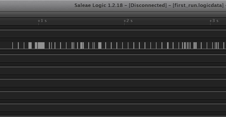
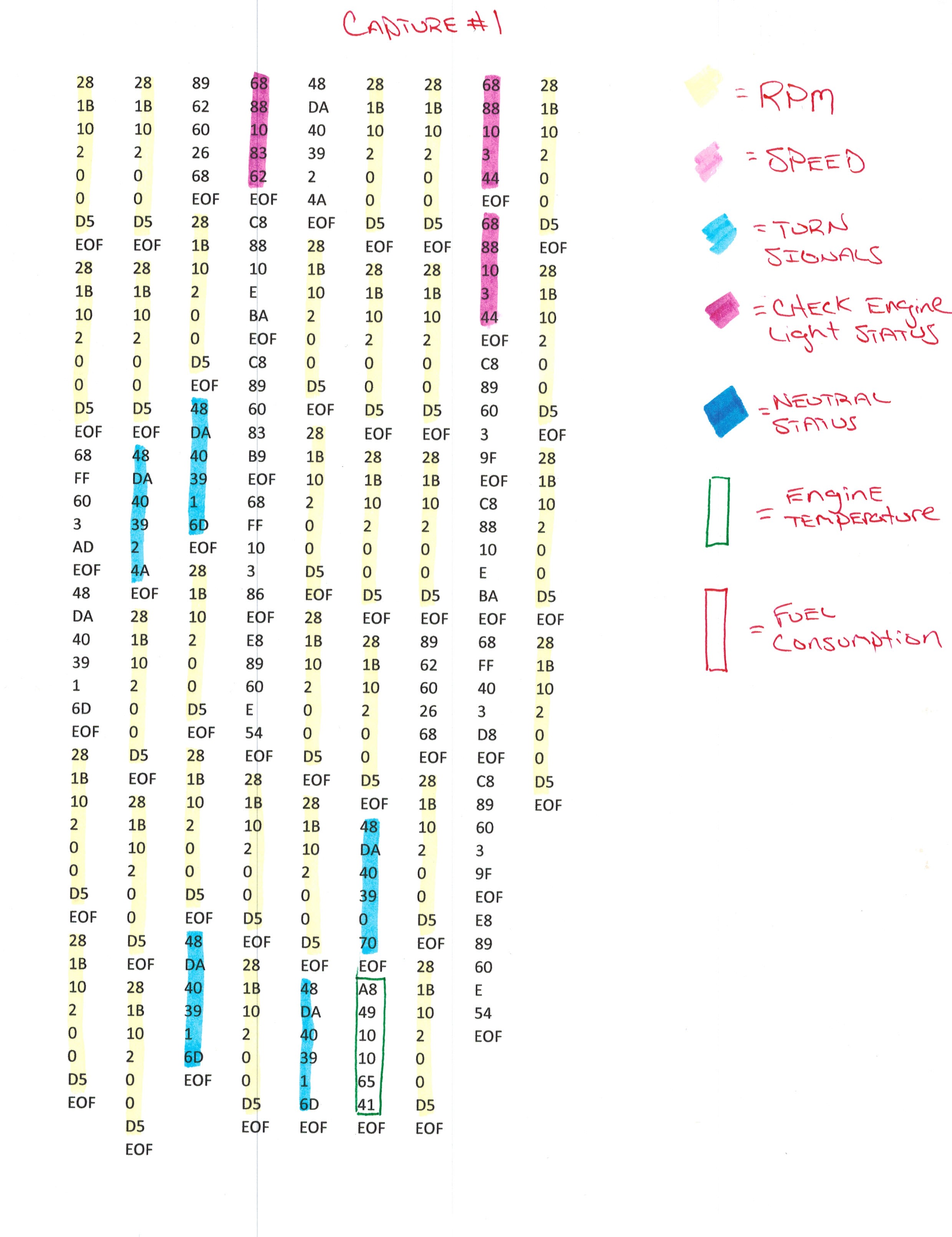
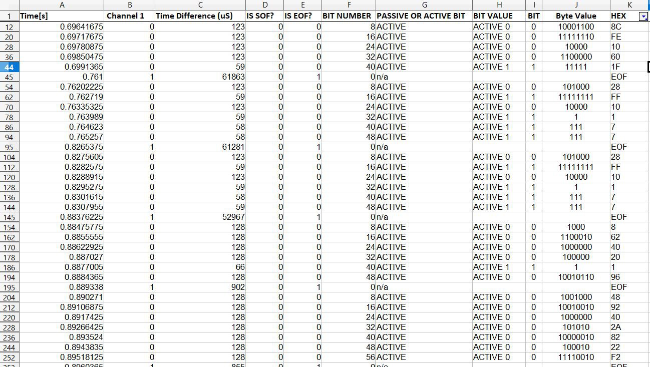 SOF and EOF are Start of Frame and End of Frame, respectively. I've begun to decode some of the data, but there is extremely little documentation, and no official documentation on what the codes stand for and mean. This could take a while...
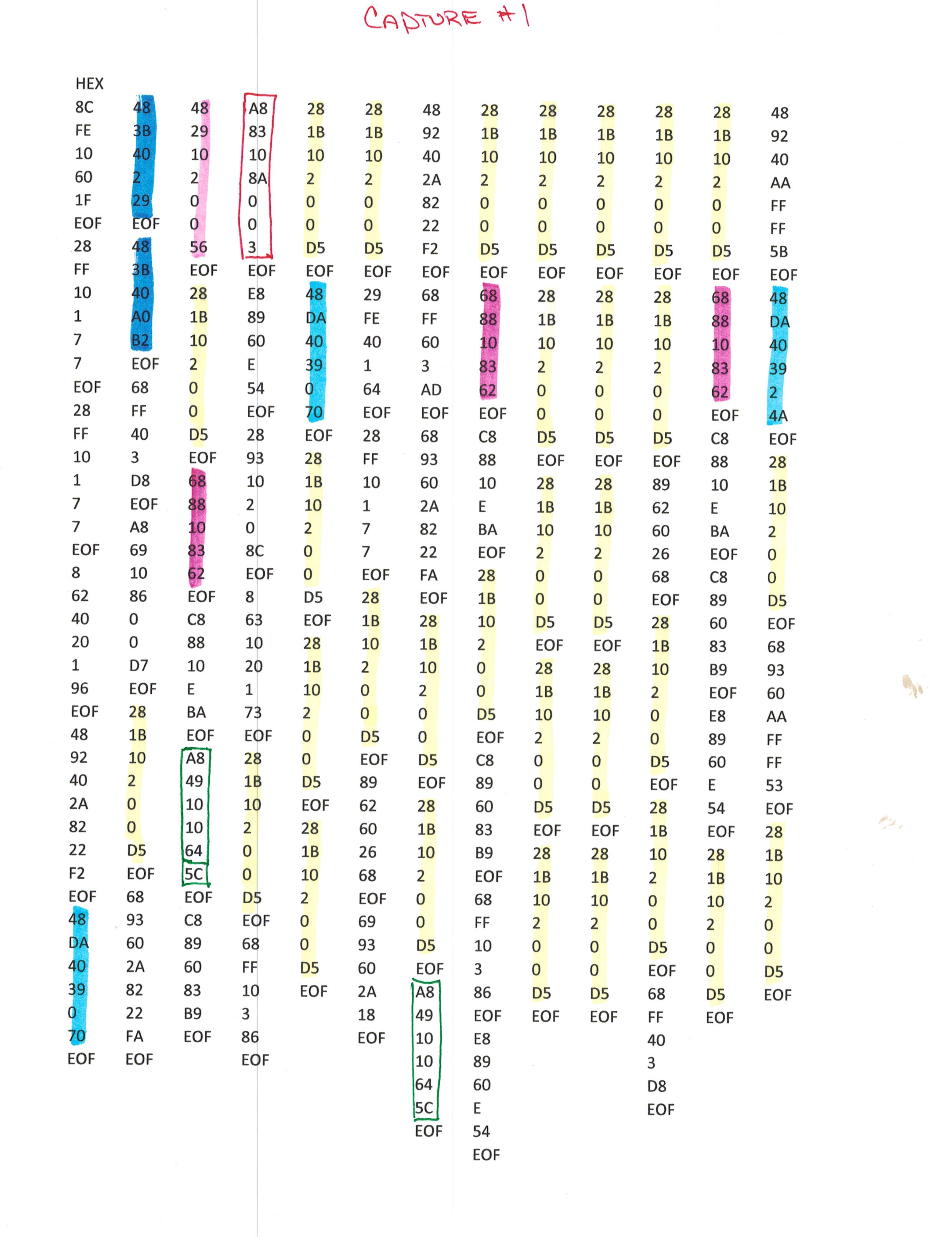

 Justin R.
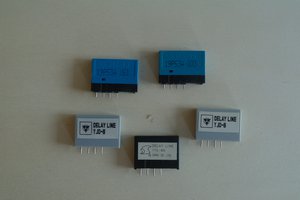
 Alain Mauer
 Peter McCloud
A visual display interface , also called a visual display unit or VDU and colloquially as a screen, is any electronic visual display device for computers. VDUs are used for visual data presentation, for example, computer monitors and television sets for computer video display, or for other purposes. A visual display unit is a general-purpose computer peripheral which generates visual images.
https://bit.ly/NrrQuO