 Michael O'Brien
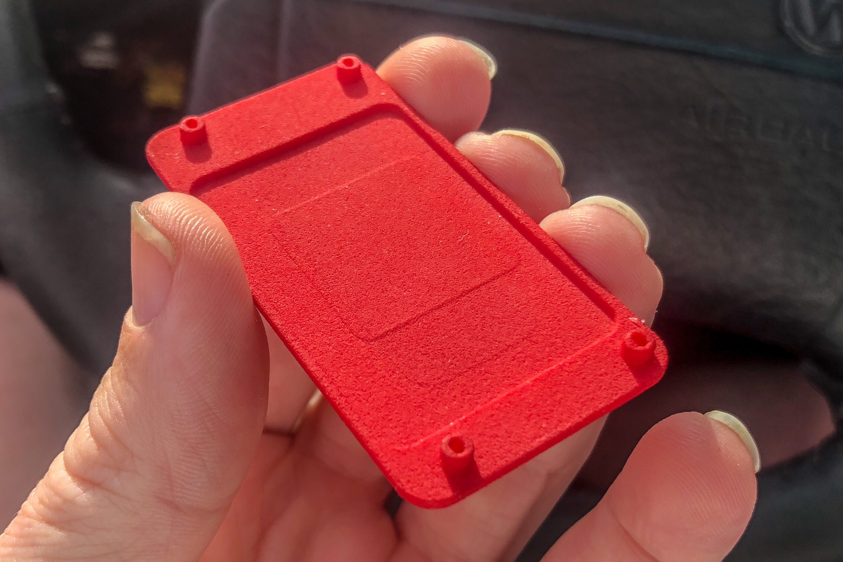
STL files don't translate well over to a machine shop for making prototypes. In my travels, I came across https://print.all3dp.com/. There are probably other, better sites, but this works well enough for what I seem to need. I took the OpenSCAD model, outputted a STL model with angles aliased to every 10 degrees, and have an SLS print in nylon on the way and it will be here Friday. I'm serious about "fixing" the cooling solution.
What's Next?
There is an EMI cage around the RAM and it creates a clearance issue for the cold plate. Also, since the cage is also screened, obstructing it will heat up the RAM. Granted, a 90 °C CPU will probably transfer more heat to the RAM than reduced airflow, but I digress.. As long as I abide by the existing 0.1" gap to minimize airflow obstruction, I can enlarge the cold plate for heat pipes at will.
In a standard heat sink, increasing the heat spreader thickness allows for more heat to be dissipated under forced convection. However, lower power outputs and thus lower fan speeds, one will see higher temps due to increased thermal resistance. There are estimation equations that will lend a hand and should give me a ~5-10% upper margin for this calculation. Even though I will not have an end result that can abide by these calculations (keep reading), I can still play around with the results to see if changes can have significant impacts on the thermal resistance.
Goal Reminder
I want an 85 °C CPU max sustained temperature in a 35 °C environment. Under peak load, this is, for the sake of argument, a 120 W load and a 50 °C differential. In other words, the thermal resistance of the entire solution is desired to be ~0.42 °C / W or more than a 60% reduction compared to stock and that's a tall order. Unfortunately, nearly all online tools for heat sinks are the standard type that you'd bolt or use push-lock fasteners to a die. None of them are cold plate -> heat pipe -> fin stack or even an analog of such.
Stock Cold Plate and Cooling Solution
There is a blank coating over the majority of the body of the cooling solution. RAW metal, albeit oxidize raw metal, has a low emissivity. The black coating, yes you can call it paint, but you will not find appropriate aftermarket products if you use the term "paint", is bonded to the metal improving the emissivity. Thus it allows the entirety of the cooling solution is passively dissipate heat, but additionally improved the efficacy of the zipper/folded fin pack/stack.
The cold plate is made up of 2 parts, a cast, then machined, aluminum chassis with an aluminum slug pressed into it. The heat pipes are then soldered onto the copper plate by a yet-to-be-determined low temp alloy. From what I've seen, it'll have a melting temp between ~140 °C and 250 °C. Indium is one of the lowest of the commonly available solder alloys and it also has one of the highest thermal conductivities, thus I assume it is the solder of choice. I have confirmed sub-0.2 ohm resistance between the aluminum cold plate and the threaded fastening points on the fin stack, thus affirming a soldered connection.
The heat pipes are 150 mm & 200 mm long from what I'd mentioned before and contact the fin stack in 2 separate placed. The fan has maximum output power of 8.4 W, aka 700 mA @ 12 V. The previous Mac mini fans were much less powerful with 1/10th the output power. As such, Apple moved to a 6-pin connector, up for 4-pin, and I need to verify that the extra two lines are for current supply.
Modified Cold Plate
I've previously uploaded a dimensionally accurate model of the cold plate of the cooling solution. It's not significant to model the heat pipes, nor the fin stack as only 1 of those can be reasonably reproduced/procured by means of 3rd parties. I've updated the model to include a red, rectilinear object to signify the clearance of the EMI cage around the RAM that is a physical obstruction.
Please use a developmental version of OpenSCAD to view the files.
- Mac mini (Late 2018) Cold Plate - Clearance.scad
- Mac mini (Late 2018) Cold Plate - SA Mod - Sine Wave.scad
The second file listed is the complete base model adjusted to have louvers in the cold plate and still clear the FCBGA-1440 package. The louvers have no function unless coupled with an inverted plate, which I still need to model. The function of this plate is to sandwich a very thin layer of TIM and a PGS, a pyrolytic graphite sheet, from Panasonic. The die has 3 cores on one side and 3 cores on the other side, along the long edges of die. Even though the PGS will not discriminate between the 'x' or 'y' directions, it stands to reason that more surface area adjacent to the long edges of the die than the short. Thus the louvered version is the Surface Area Mod.
Apple did design in manufacturer tolerances to the cold plate mounting since soldering the heat pipes into a precise spot on the cold plate isn't exactly precise. This modified model does not have similar tolerances designed into it at this time and is only meant as a starting point to work from. The only other notable change is an increase from ~0.5 mm to ~1.0 mm thickness of copper the h=thermal flux has to flow through before reaching the heat pipes, if soldered directly to the flat surface.
Obligatory Renders of Both Cold Plates
- Stock
- Modified Base
%20Cold%20Plate%20-%20SA%20Mod%20-%20Sine%20Wave%20-%20Top.png)
%20Cold%20Plate%20-%20SA%20Mod%20-%20Sine%20Wave%20-%20Bottom.png)
Post Script
As-is, the SA Mod cold plate being lost-wax cast, or so they say, in copper will cost anywhere from $90-$105 in the current arrangement, with shipping. Since I've extended the flat portion of the contact surface to the length of the cold plate and it has a thickness of 1 mm, there is plenty of room for reducing the volume of copper used and reducing the cost.
Dimensional Check
With the arrival of that test print, I did update the dimensions/locations of a couple of things. I have also moved those photos to here.

Discussions
Become a Hackaday.io Member
Create an account to leave a comment. Already have an account? Log In.