Close
0%
0%

Discontinuity / Continuity Tester

Turn on a light and optionally a beeper for continuity (conduction) or for discontinuity (open circuit)

Similar projects worth following
This is a continuity/discontinuity tester. It turns on an LED and optionally a beeper for test circuit continuity (conduction) or for discontinuity (open circuit, also called reverse continuity). This was created primarily for the discontinuity function which is useful when testing for a temporary or intermittent open-circuit condition.

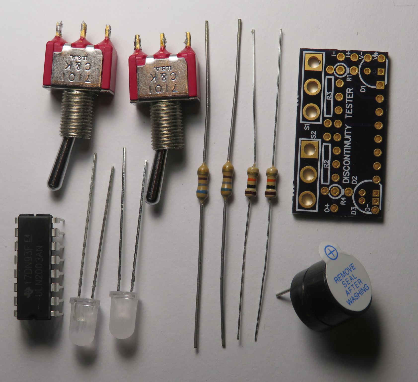
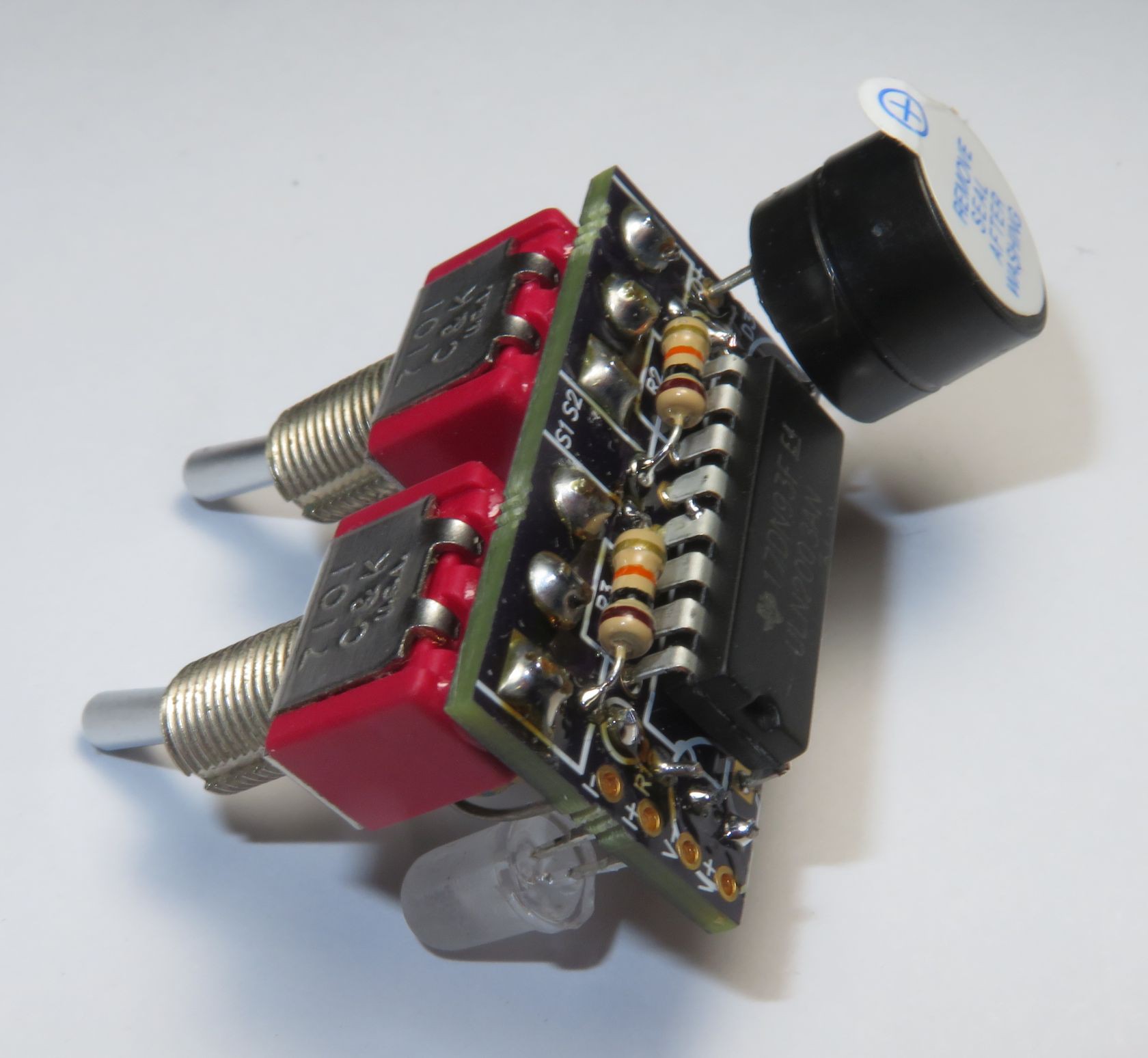
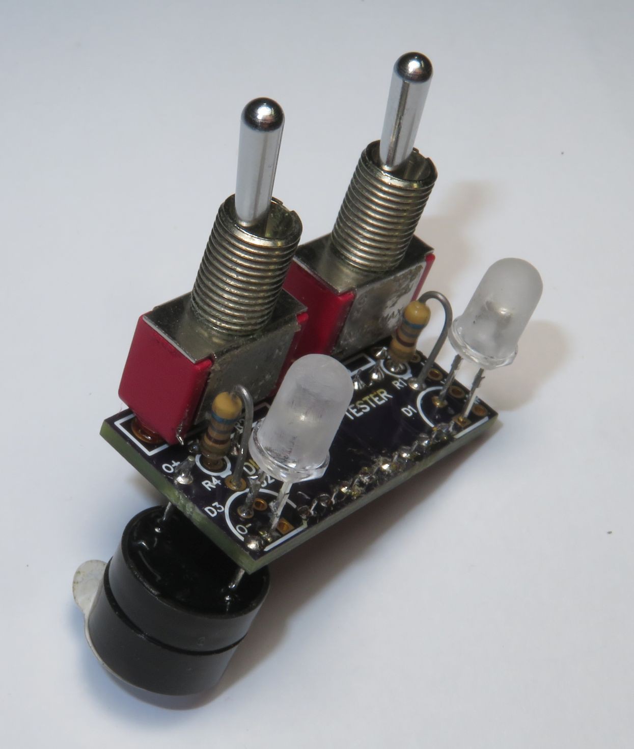
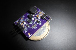
This can be powered by voltages in the range of 3.3 to 12 V or more but component values below are for a 5 V power supply (not included).  The circuit board design is on OSH Park at https://oshpark.com/shared_projects/fKoGMBCK.  This does not use a microcontroller so no program downloading is required.  The main circuit element is a ULN2003A Darlington transistor array (16-pin DIP).  The board is small to minimize board cost.  Board mounting is intended to be done via the two panel-mount SPDT switches.

One switch (S1) is used to select between the continuity and discontinuity functions.  The other switch (S2) is used to enable or disable the beeper.

The tester's positive test input terminal is the power supply and it's negative input test terminal is a ULN2003A input as described below.  There is no extra circuitry for current-limiting, ESD protection, etc. (KISS principle used).

Build Options:

  • LED D2 or D3 should be populated but not both because they share the same current-limit resistor and overlap on the PCB.  D2 lights for test circuit continuity regardless of the setting of switch S1.  D3 lights depending on the S1 continuity/discontinuity setting.
  • Switch S1 can be a SPDT Center-Off instead of a normal SPDT to combine the function of S2 (beeper on/off) into S1 (continuity/discontinuity).  However, the center-off position changes the behavior by disabling LED D3 in addition to the beeper.  If the center-off switch option is used, a jumper needs to be installed between S2 pins 1 & 2 in lieu of the switch.
  • The beeper, the LEDs, or the switches can be remotely mounted instead of directly mounted to the PCB.
  • A power switch could be added to the enclosure to save power -- useful for batteries but very little power savings if powered by AC.  The power-on LED D1 (and R1) is not required and could be omitted.
  • This could also be used to show the state of a digital output by connecting the digital output to the input negative and the digital output's ground to the power supply negative/ground.  The digital output must source current -- if it's an open-collector type output, a pull-up resistor must also be added.

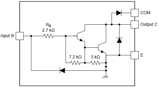
Key specifications of the ULN2003A Darlington transistor array are:

  • Input current-limit resistor going to the base, 2.7 kOhm nominal.
  • Input pull-down resistor to ground, total of 10.2 kOhm nominal.
  • Because it is a Darlington, output saturation voltage is > 0.6 V and there's two diode voltage drops on the input before it starts conducting.
  • Minimum operating voltage is limited by the input resistance and the transistor gain of >1000.
  • Maximum operating voltage is limited by the 50 V Vce specification.

If a different power supply voltage or different LEDs are used, the LED current-limiting resistors (R1, R4) may need to be changed.  The most accurate way to determine the resistor value is to use an adjustable power supply, a DMM, and a 100 to 1000 Ohm resistor.  Hook the resistor in series with the LED and the DMM across the LED. and set to measure voltage  Then change the power supply voltage until the desired brightness is reached.  Then measure the LED voltage.  Then set the DMM to measure current and put it in series to get the LED current.  Then use Ohm's law:  R = (Vs - 0.6 - Vled) / Iled, where Vs is the power supply voltage that will be used, 0.6 is approximately the ULN2003A Darlington transistor voltage drop, Vled is the LED voltage drop, and Iled is the desired LED current.  Use the nearest available resistor value; precision is not required.


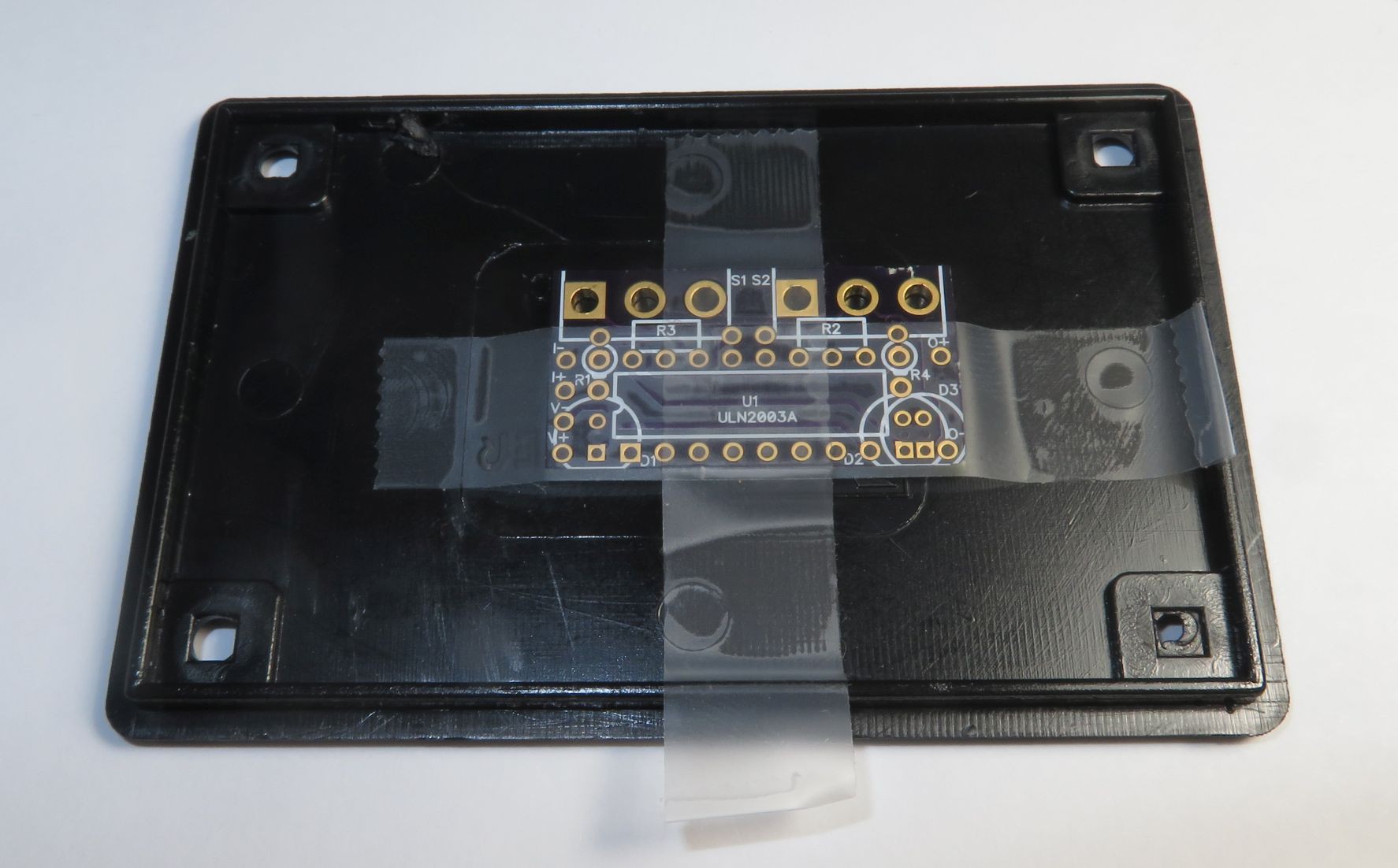
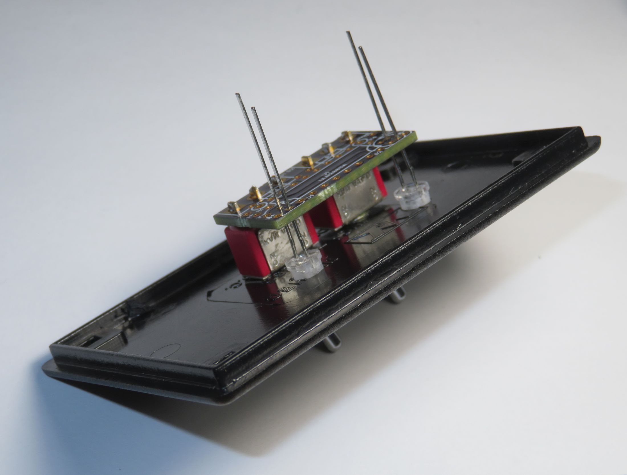
The PCB side with IC U1 ULN2003A is called the top side.  The IC must be mounted on the top side for the PCB interconnections to be correct.  All the other components can be put on either side or mounted remotely instead of on the board.  What works well is as shown below: IC, beeper, R2...

Read more »

BOM.xls

Parts List, includes a set of part numbers

Microsoft Excel - 10.50 kB - 12/23/2018 at 13:41

Download

Discontinuity Tester PCB.pdf

PCB, Pictorial of both top and bottom (see thru)

Adobe Portable Document Format - 16.46 kB - 12/21/2018 at 17:44

Preview
Download

Discontinuity Tester Sch.pdf

Schematic Diagram

Adobe Portable Document Format - 25.96 kB - 12/20/2018 at 06:40

Preview
Download

Gerbers.zip

Gerber Files

x-zip-compressed - 7.97 kB - 12/20/2018 at 06:38

Download

  • 1 × D1, LED, T1-3/4, Red or Green or Other LED for power-on indication, hole diameter: 0.711 mm (.028")
  • 1 × D2 or D3, LED, T1-3/4, Green or Red or Other LED for discontinuity/continuity indication, hole diameter: 0.711 mm (.028")
  • 1 × R1, Resistor, Axial, ~1/4W, 50-1000 Ohm depending on power supply, LED Current-limit resistor for D1
  • 2 × R2, R3, Resistor, Axial, ~1/4W, 470-20000 Ohm, noncritical value Pullup resistors
  • 1 × R4, Resistor, Axial, ~1/4W, 50-1000 Ohm depending on power supply, LED Current-limit resistor for D2/D3

View all 10 components

  • 1
    Plan

    Decide on what configuration to build – switch options, LED options, power supply type and voltage.  Get the components, including non-PCB components like a box, test probe connections, and power source.

    In my opinion, LEDs with white diffused lenses provide the best contrast and most uniform viewing angle, but they are not widely available.  I made clear lenses into diffuse lenses by scuffing up the lenses with sandpaper or an emery board.

  • 2
    Drill Front Panel Holes

    Tape a PCB to the front panel to use as a drill guide for drilling holes in the front panel.  It works best in my opinion to have the IC (U1) and the top side of the PCB facing inward as shown in the photos.  Drill initial holes smaller than the final hole size.  For the switch(es), the PCB hole size is 2.1 mm (.083”), so use a #45 (.082”) or similar drill in the center hole of the switch.  For the LEDs, there are little 0.5 mm (.020”) holes centered on the LEDs between the LED pads.  Too big of a drill will compromise the LED pads, so use a very small drill if you want to use the board to build a tester.  Once the initial holes are drilled, untape the PCB from the front panel and drill the holes to the final size.

    Drill other holes for test input connections and power supply.

    Fit the PCB, switches, LEDs, and front panel together for fit.  Make any adjustments needed, for example hole sizes.  Then take apart.

  • 3
    Add components to PCB

    Assemble the PCB.  Suggested ordering and PCB side for soldering components is:

    • IC U1, top side

    • Resistors R2, R3, top side

    • Resistors R1, R4, bottom side

    • Switches and LEDs S1, S2, D1, D2/3, bottom side. Fit into PCB, then fit into front panel, then solder, then remove from front panel. Be sure to put the LEDs in the correct way. The longer lead is ‘+’ and goes away from the edge of the board. The flat on the LED body goes near the edge of the board.

    • Beeper/buzzer into holes labeled O+ and O- if mounting directly to the PCB. Observe polarity, the longer lead is likely ‘+’.

    • Power supply connections to V+ and V-, and test input connections to I+ and I-. Or assemble into the enclosure before soldering these.

View all 4 instructions

Enjoy this project?

Share

Discussions

Similar Projects

Does this project spark your interest?

Become a member to follow this project and never miss any updates