 MaBe42
Two wires in circular shape form the base of a ball-like object.
One of these circles serves as ground the other provides the supply voltage.
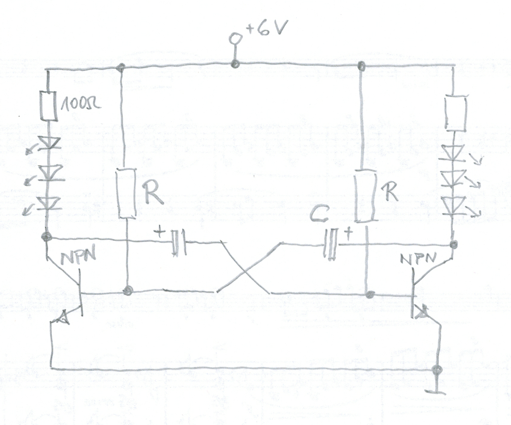
I built ordinary astable multivibrators. One with 100k and 47uF, the other with 180k and 33uF to have slightly different blinking frequencies. In each of these two independent circuits three LEDs and a 100 Ohm resistor are wired in series.
The coin cell holder is also bent from wire and soldered to small piece of PCB (comprising just three holes) for stability reasons. I added a two pin male connector and a jumper as switch.
To facilitate soldering I used hot glue to put the circles in place. When everything was finished I removed the glue and connected the wire ends of each circle with a short piece of grey cable isolation for stability and to avoid shorts.


 Cristi Ingineru
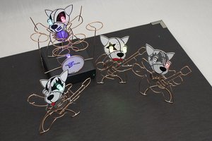
 Roger
Roger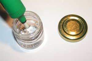
 RoGeorge
 Ted Yapo
Thanks. I was also considering the 555 at first. But it would require about the some number of components. So I went for the very basic design. I just added the schematic and some building instructions. I will add some details about the battery holder, later. Probably not before next week.