 RobsonCouto
Now that the microcontroller seems to be working fine with the other components, it is time to find a power source. I bought this 3.7 lipo battery for powering the robot, it is quite light and provides enough voltage and current to power the circuit.
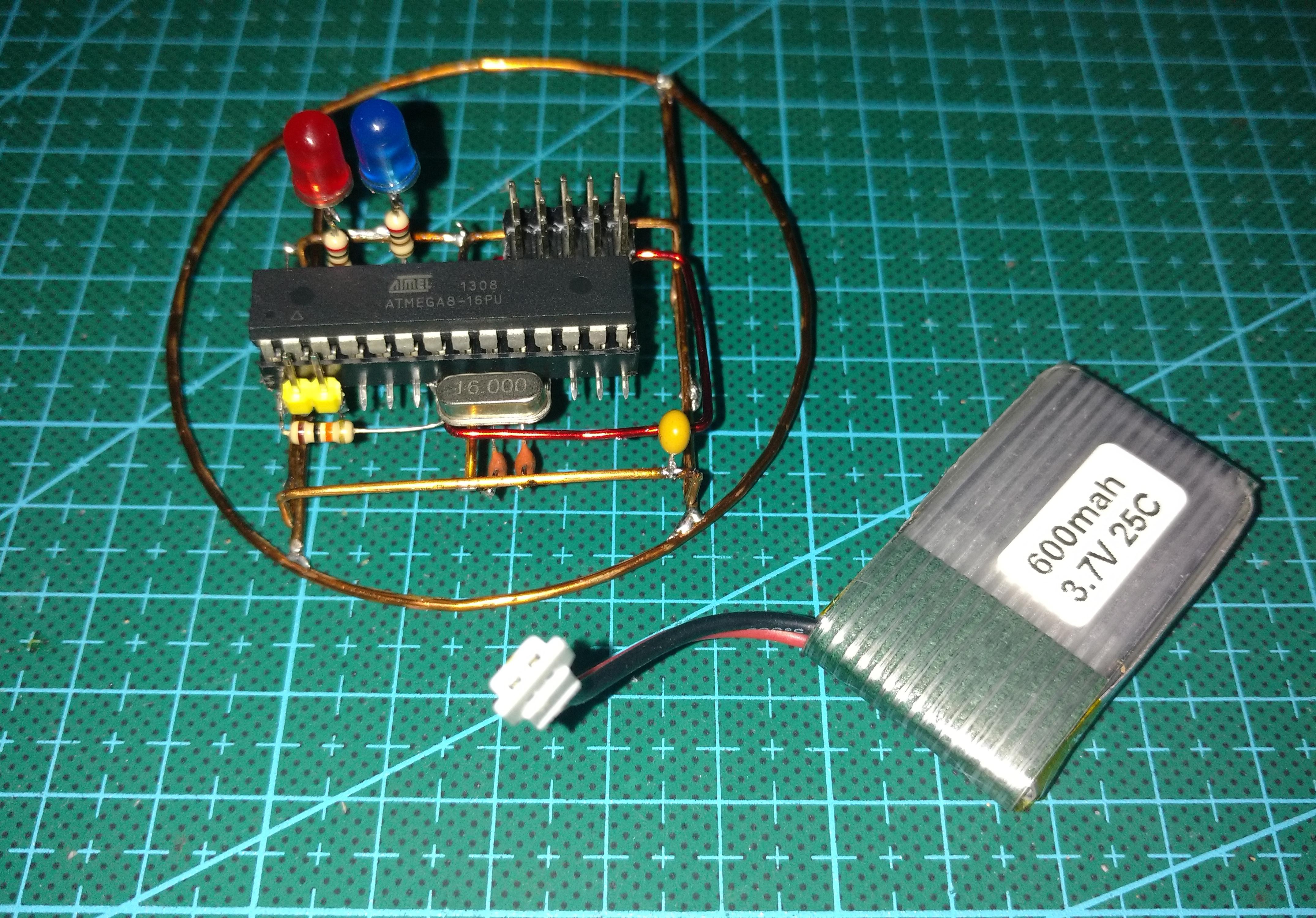
The circuit seems to work fine with just 3.7V, so I am glad I don't have to add in a step-up circuit, that would be a power waste and would not match the overall look of the project.
Lipo batteries are know for causing trouble, so I have to take at least some care. These batteries cannot over discharge, so I use a free analog pin to monitor the voltage of the battery, which can somewhat represent the battery charge.
I added a resistor divider (not seen in the picture, as it is under the microcontroller) connected to an analog pin. This resistor divider halves the battery voltage (4.2V max), which is then read by the microcontroller (2.1V max). As the battery voltage changes, the internal reference of the microcontroller is used instead of VCC. Thankfully, Arduino allows one to easily change the voltage reference of the microcontroller's ADC without direct register manipulation. So I use:
analogReference(INTERNAL); //sets the ADC reference to internal 2.56V reference
Note: The ATmega8 has a internal reference of 2.56V, but most of the AVR Arduino boards actually have a 1.1V reference.
As the battery voltage (3.7 - 4.2V) is higher than the internal reference (2.56V), we need some trick in order to measure it. I have used a simple resistor divider. I used these blue resistors, which I despise because I cant read them without a meter, but have good precision (1%). Two 10K resistors split the battery voltage to a max of 2.1V. Sweet.
To get the voltage measurement from the ADC, we multiply the value read by two(because of the divider), then by 2.56V divided by the resolution of the ADC (1024). This is done with the following line of code:
battery_level = (analogRead(A1)*0.005);//0.005=2*2.56/1024;
I plan not letting the battery voltage get any lower than 3.7V, so when that voltage is achieved, the robot will stop the motors and start to blink the LEDs, warning that the battery should be charged.
I still have have to add a power switch to the circuit, and I am also at the moment looking for options for reverse polarity protection. I have had bad experiences with plugging batteries the wrong way in the past, and would not like another one. My options are limited to the components I have at the moment though, as the deadline of the contest is approaching.
Discussions
Become a Hackaday.io Member
Create an account to leave a comment. Already have an account? Log In.