 matseng
Making the 24 rings (16 for the address bus, and 8 for the data bus) rings was fairly easy. I just wrapped each ring around tin of paint that had a good circumference and snipped off the end of the wire (while stil on the tin) so that the ends overlapped 5 mm and then dabbed a small dot of flux and soldered the ends together.
Since I've got a nice Metcal soldering station and a really fat tip for the iron I could solder the joint in less than a second of dwell time. This means that I could use my fingers to press down on the wire very close to the joint without burning myself. Sometimes it pays off to invest a bit extra in good tools. :-)

I think I'll make a few more rings with a slightly smaller radius to use as a VCC/GND bus and put them in between the two other buses - behind the ICs.
I've been thinking of how to put the rings into a structure. I could 3d-print some plastic structures that looks like giant combs like this (I already had this one laying round from another project):
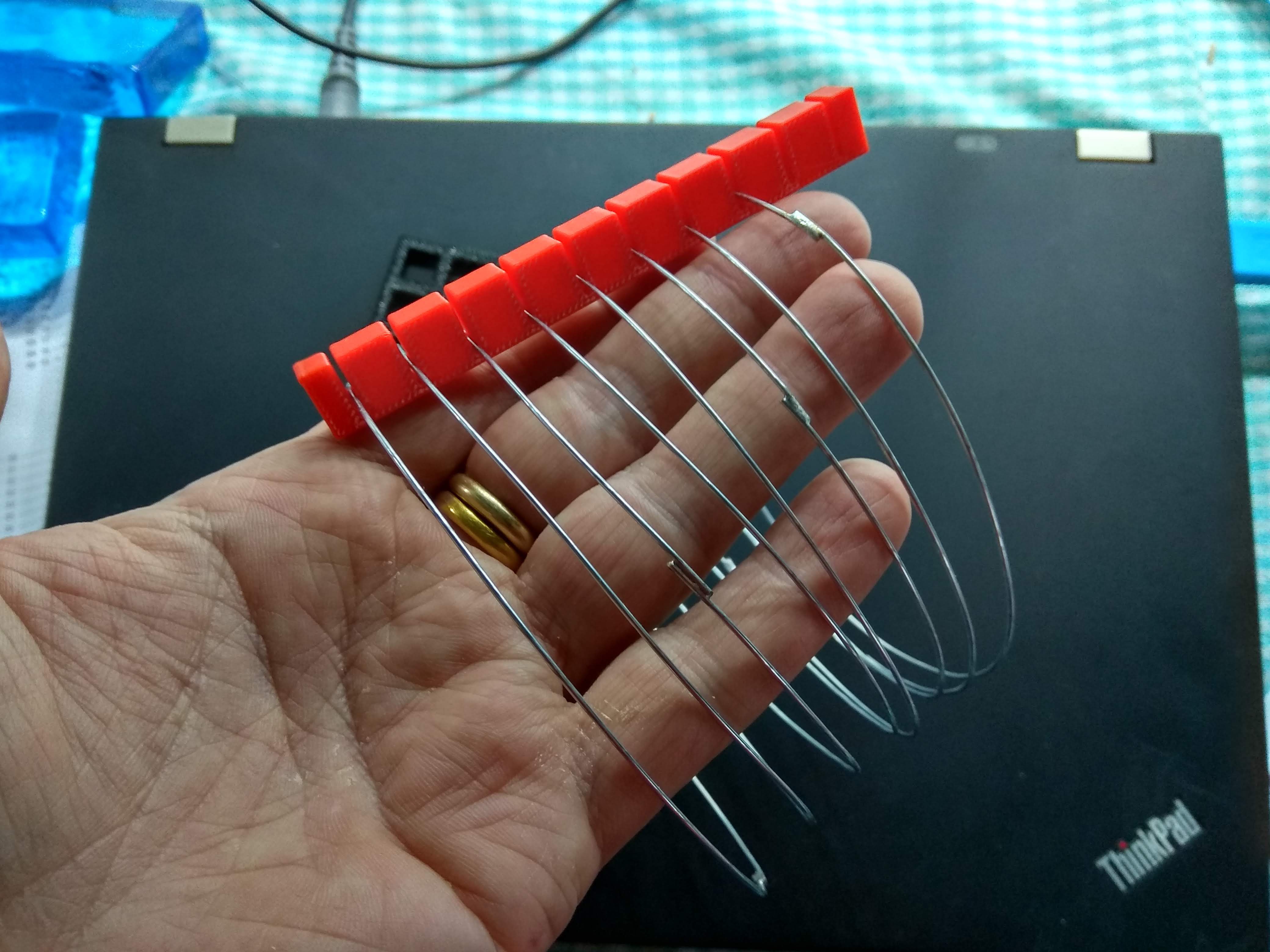
But it wouldn't be kosher to have ugly plastic parts for structural integrity in this project. Maybe pretty laser cut acrylics would be ok, but I don't have a laser cutter so that's not an option.
If I had a buttload of 1pf ceramic caps in my part cabinets I could just solder three of them between each ring as spacers. Considering that a Z80 machine works just fine on a breadboard that will add 4-5 pf between the lanes a couple of pfs here wouldn't be the end of the world.
But I don't got that many super-low value caps at home either. But I got plenty of small 1M resistors. Using three 1M in parallel gives 300K. So there will be like having a 300K resistor between DB0 and DB1, between DB1 and DB2 and so on. A lot of crosstalk going on. But I'll go out on a limb here and just assume that 300K is so high that the drivers in the ICs will be able to cope with that with their hopefully "superior" current driving capabilities.
It probably would have been better to use 10M or even 30M resistors, but.....
Discussions
Become a Hackaday.io Member
Create an account to leave a comment. Already have an account? Log In.