 matseng
I thought it was a real 27C512 UV EPROM I had in one of my junk boxes, but after peeling off the sticker on top of it it turned out to just be a OTP PROM. I'm definitely not confident that I'll be able to make the firmware 100% working at the first try so I had to come up with a solution for this.
I have some extra SRAMS laying around so I used the project at https://hackaday.io/project/8109-sram-as-replacement-for-eprom as a basis for my battery backed SRAM that emulates a 27C256 EPROM.
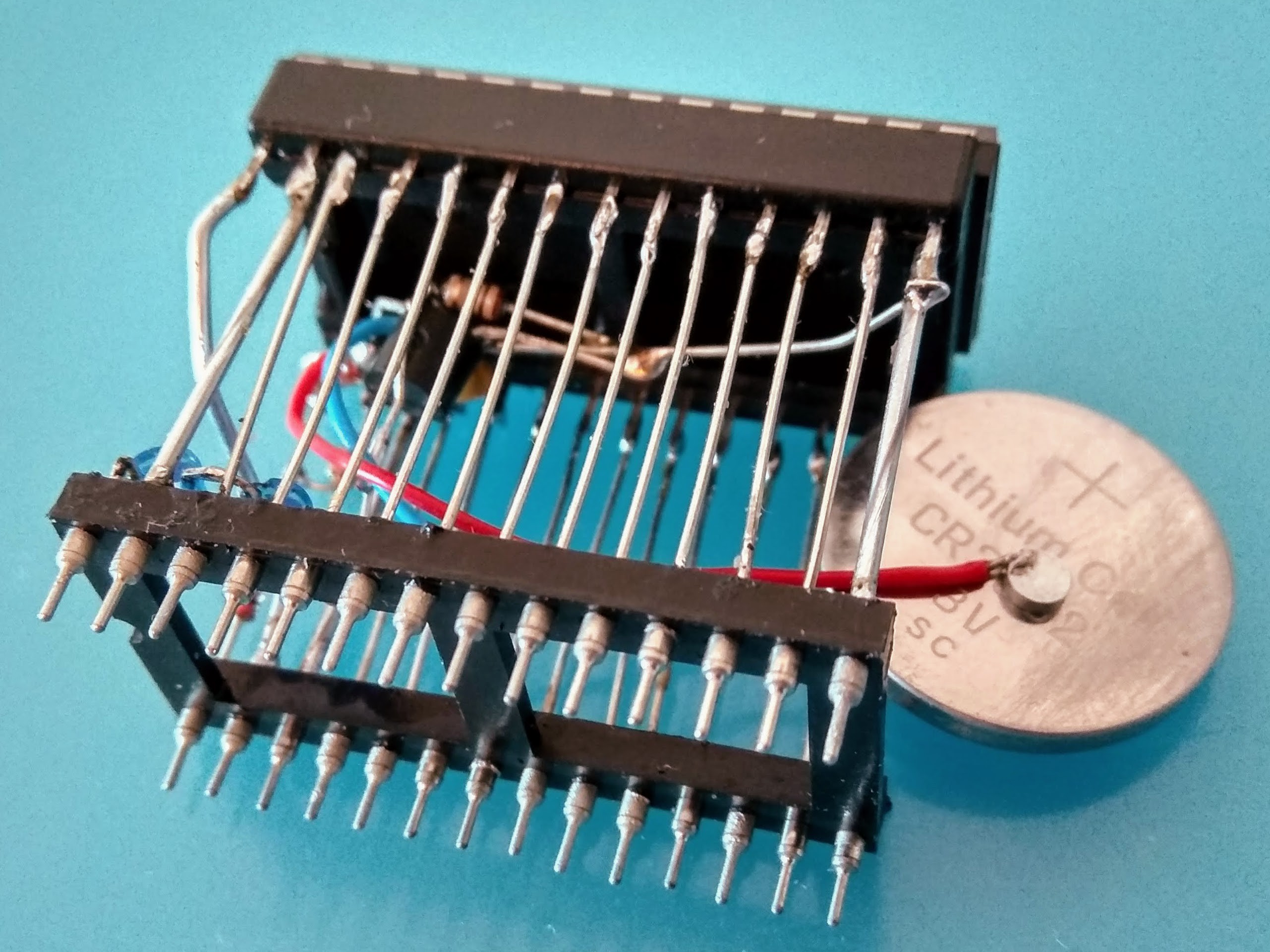
Since I didn't have any super capacitors and self-discharge of the 2200uF I already had at hand indicated that they would be flat inside 24 hours I decided to use a CR2032 coin cell battery as the backup power for the RAM.
The next setback was that I couldn't find a battery holder in my drawers, I tried to solder wires directly onto it. I've seen it be done, but I couldn't get the solder to wet the battery casing even if I used a fat tip on the iron and aggressive flux. I even tried to lightly sand the surface down a bit before soldering - but no joy.
I ended up soldering the wires to two neodymium magnets instead. Of course soldering on a magnet is not a good idea, since one easily reaches the Curie temperature which will kill the magnet permanently (pun intended) dead. But by soldering really fast to an edge while keeping the bulk of the magnet cool by holding it with tweezers I was able to solder wires to them while still having enough magnetic force left in them to be able to stick fairly good to the battery.
")
The schematics for my version of the battery-backed SRAM looks like this. Compared to the super-capacitor variant I've just added a diode between the battery and the SRAM to keep the external VCC trying to "recharge" it - I'm sure the battery would be mightily upset by that and express its anger in some fireworks and smoke sooner or later ;-)

After soldering it up it looks like this and can be programmed using my TL866 - I just have to remember turning off the Chip-ID function of the software since it actually puts out 12 volts at A9 - the SRAM probably won't survive that. I probably should solder in a clamping diode between A9 and VCC on the SRAM to keep it safe(er) from being electrocuted into oblivion by my forgetfulness.
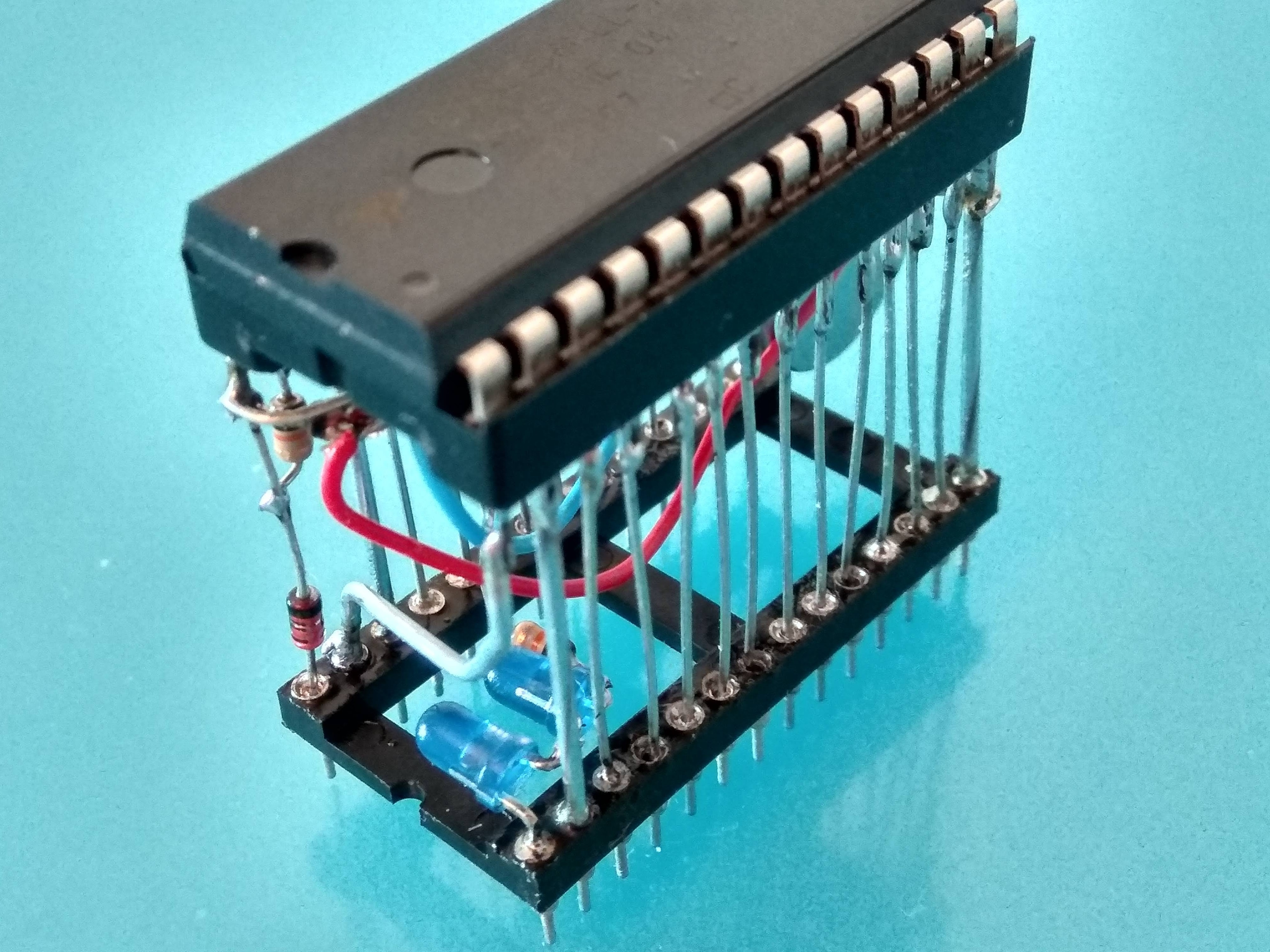
And yes - I did wrap some tape around the battery before tucking it into between the sockets....
Discussions
Become a Hackaday.io Member
Create an account to leave a comment. Already have an account? Log In.
About soldering onto magnets... It’s not necessary. :) Solder the wire onto a small metal plate, stick the magnet to the plate, stick the battery to the magnet. Done!
Are you sure? yes | no