 Quinn
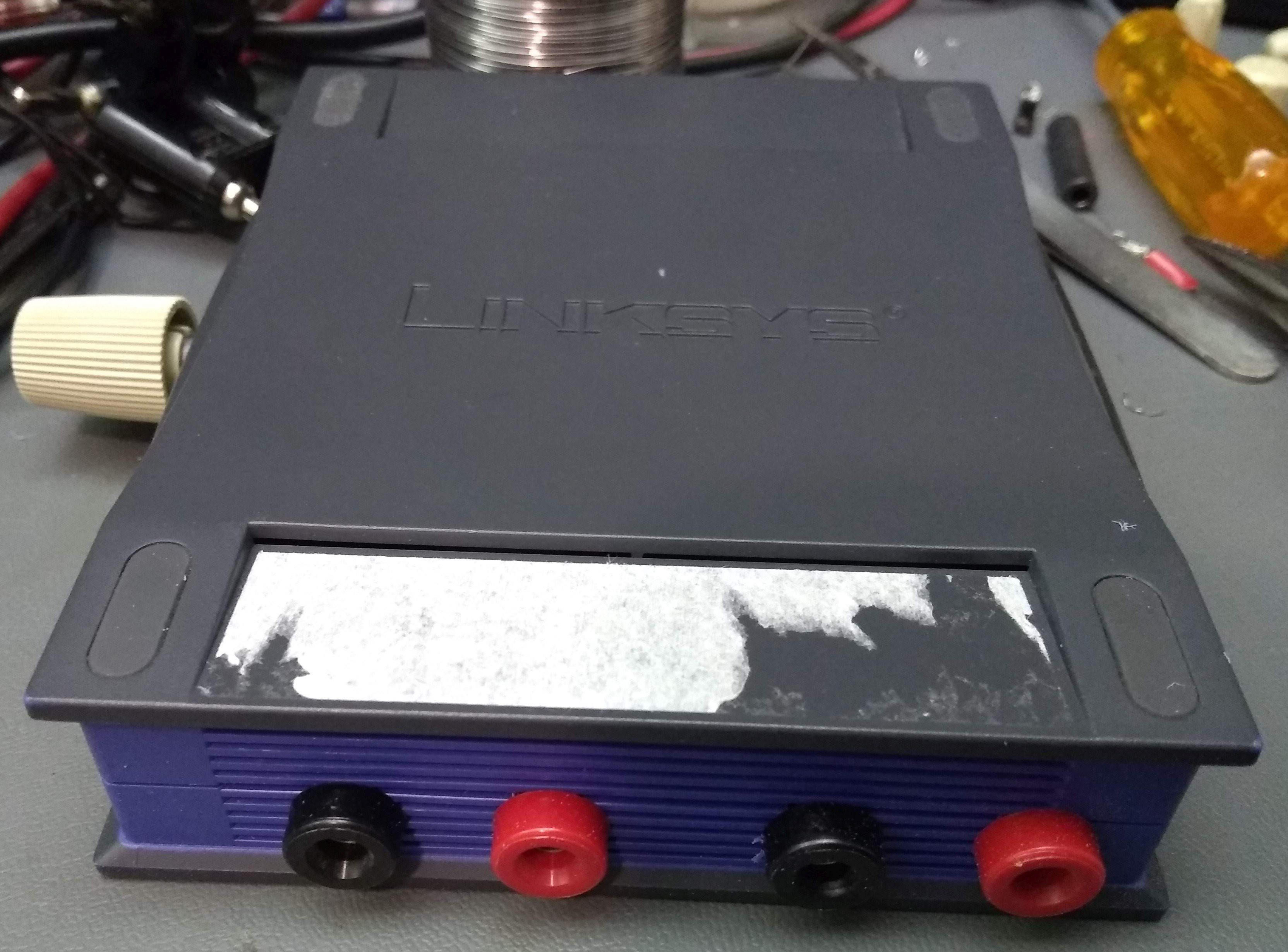
QuinnFor a case, I needed something plastic in order to allow the internal bluetooth antenna to work. I ended up using a small Linksys router I thrifted for $2.
Outputs
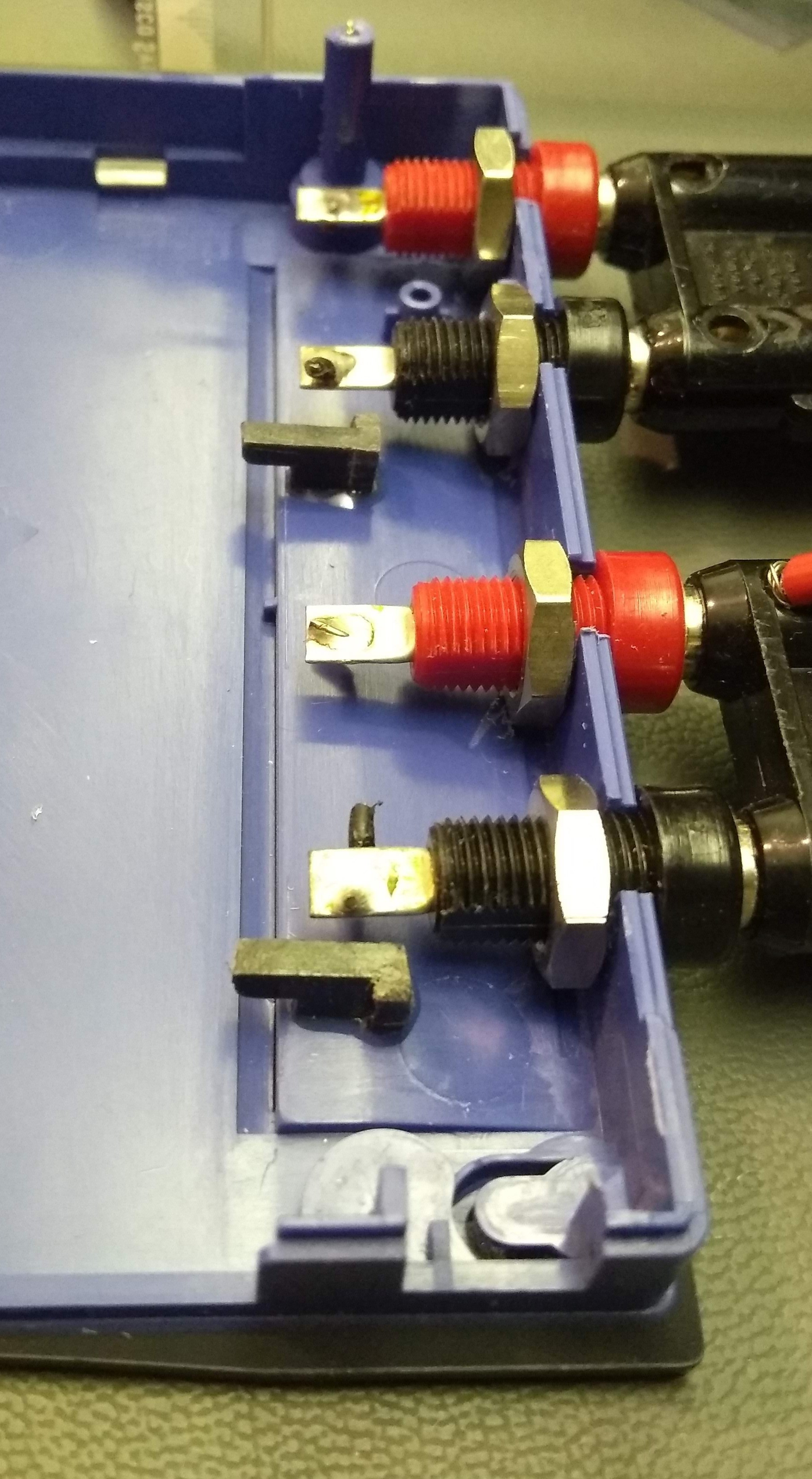
I selected banana sockets for my output terminals, and mounted them on one edge, 0.75" center between +/-, and 1.0" between the pairs. This spacing is to allow a dual plug to be used, but also to prevent a dual plug from accidentally bridging between the channels. These sockets have a double-D shape to prevent rotation and a nut. I used a rotary tool to cut these slots, and mounted them. (picture taken at the end)
Note that the negative output is not ground as the speakers are driven with an H-bridge circuit.
Volume
To make it fit in the case, I mounted the volume knob along another side. I intentionally left space for a switch and line input if I ever wanted to add those in the future. (I wanted to, but don't want to spend the time right now) There is a small plastic frame on this side which used to frame the ethernet jack. I cut a rectangular "washer" to fill over this space using galvanized sheet steel. This was later epoxied onto the plastic to make it easier to get together. Drilling the hole in a strip of thin metal like this required sandwiching it between two pieces of wood and drilling all the way through so that the bit didn't grab and rip the steel.
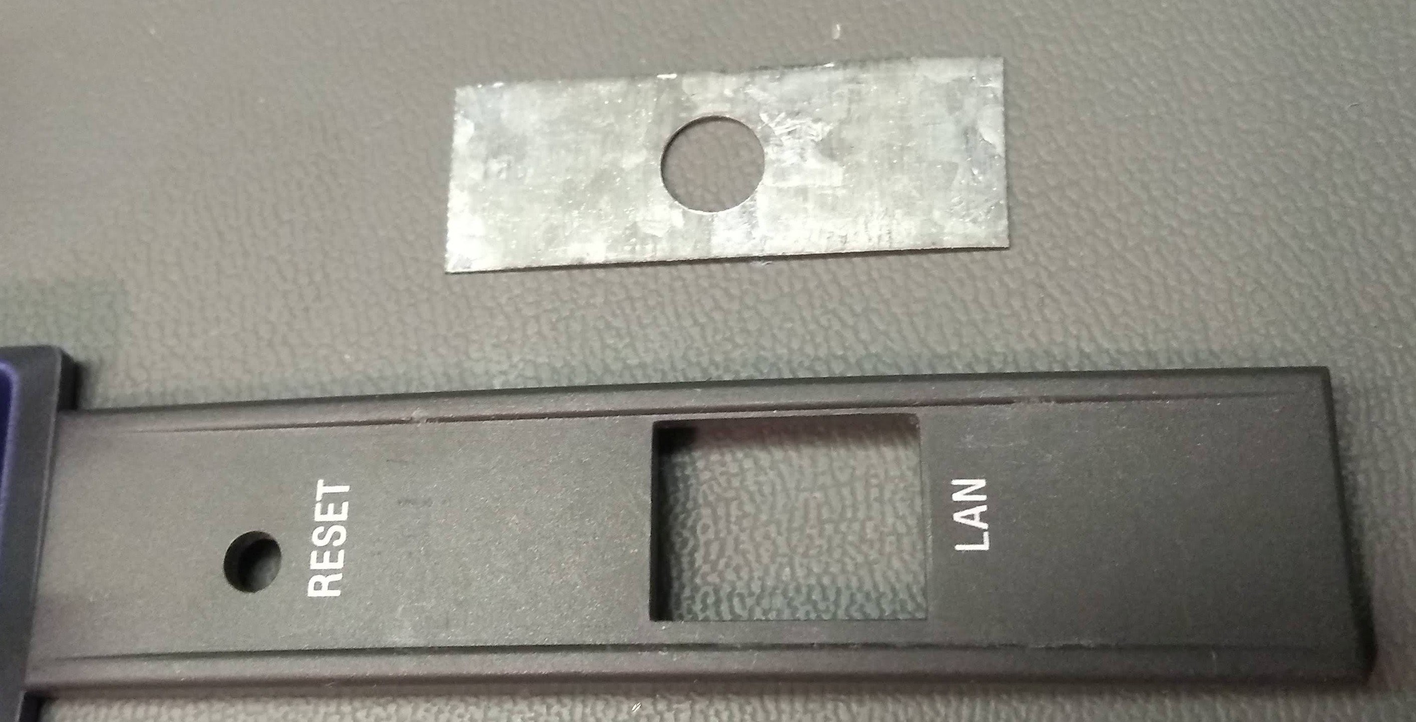
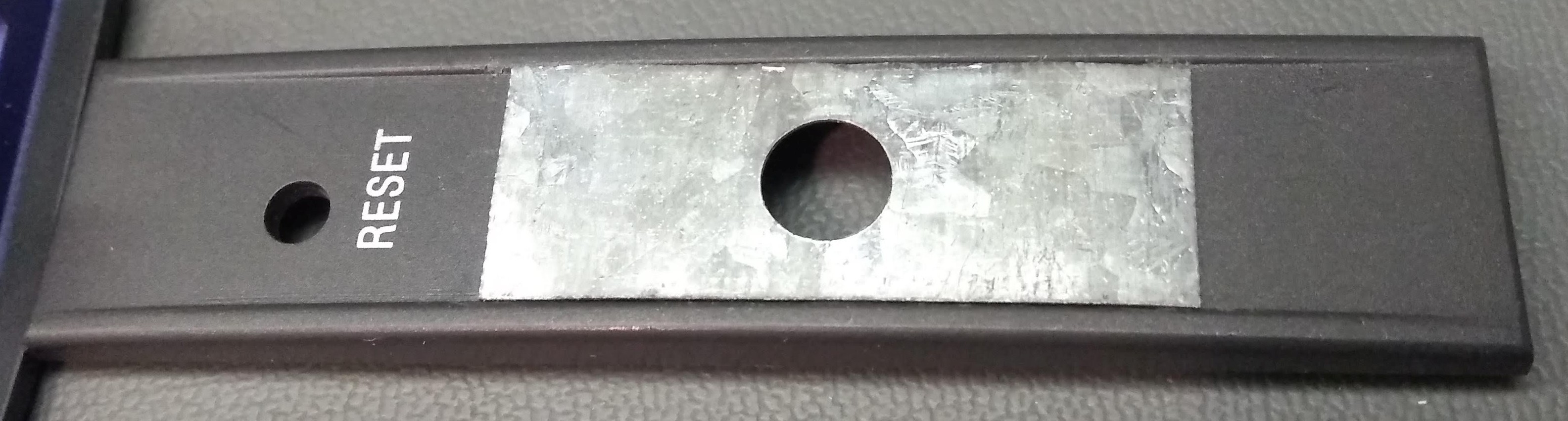
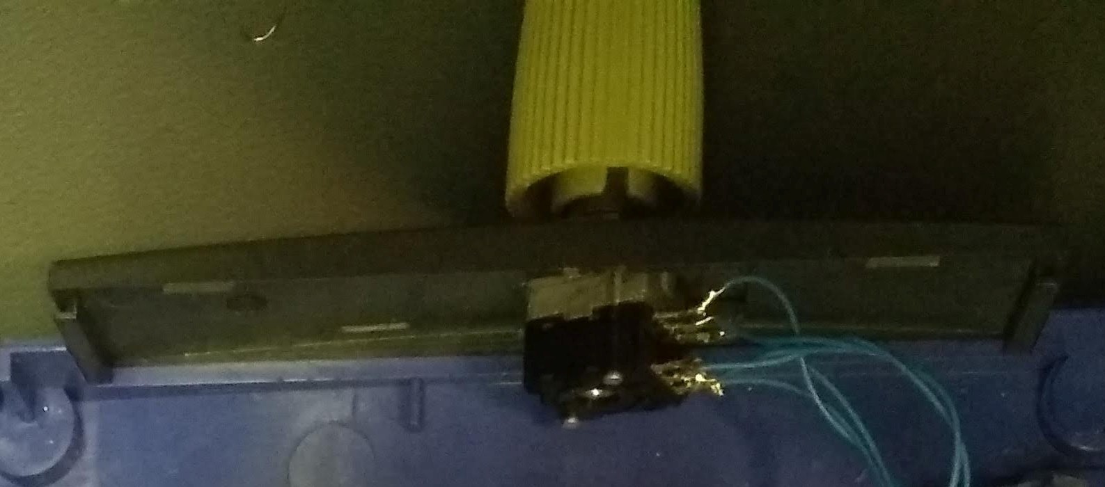
The potentiometer simply went through the hole with a nut holding it in place from the outside.
Board mounting
The case didn't have any screw bosses that I could use so I needed to come up with my own way of holding the board in. On one side, the board could lay on a shelf which was held down by the other case half. This would allow the DC jack on the amplifier to be at the edge of the case so I wouldn't have to relocate it, simply cut an opening.
However the other side was still floating. I cut some hooks out of the plastic from a different router and glued them into the case. This allowed the board to be slid under those hooks and layed down oh the shelf on the other side.
LEDs
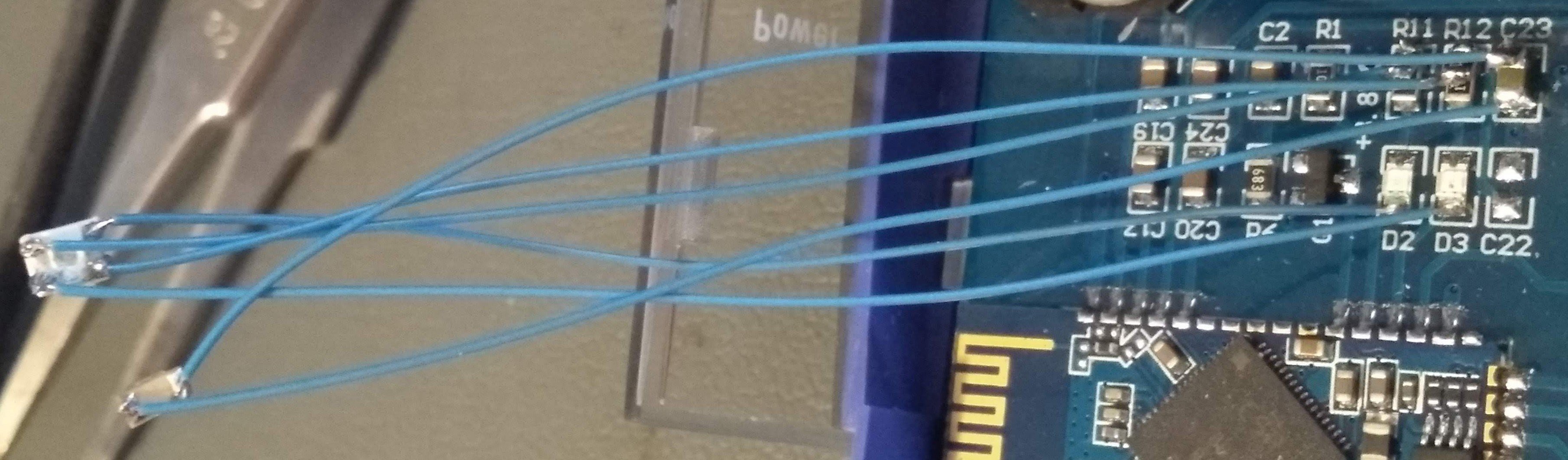
The amplifier has two LEDs on it. The Blue one, D2, flashes 3 times about once per second when a bluetooth connection is made. The Red one, D3, flashes 2 times about once per second when a bluetooth connection is lost(only after it was initially made). After power up and before any connection is made, they will rapidly flash alternately. As they are handy, I wanted to be able to see them on the outside as well. Instead of desoldering them and moving them, I just left them on the board, and paralleled additional LEDs. Note that they are not paralleled across the LED itself, but instead, a new LED and new resistor were paralleled across the original LED+resistor. Looked at another way, I tombstoned a new resistor on the 3.8V rail(where the original LEDs were powered from), then ran a wire from that resistor to the LED, and back to the BTM825 pin.
I chose to use a dual color red/green led I had from stock, connected to both the board blue and red. I also added a green led which was simply powered from the 3.8V rail to ground to act as a power indicator.
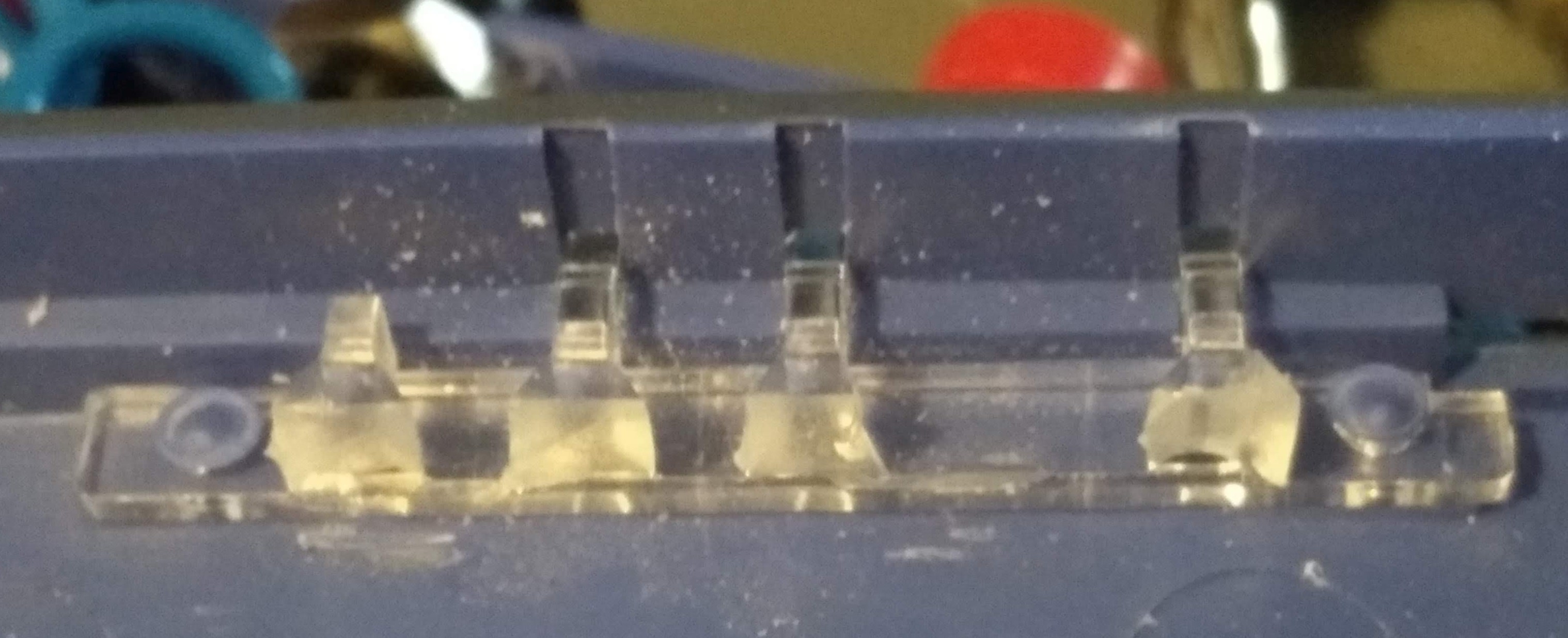
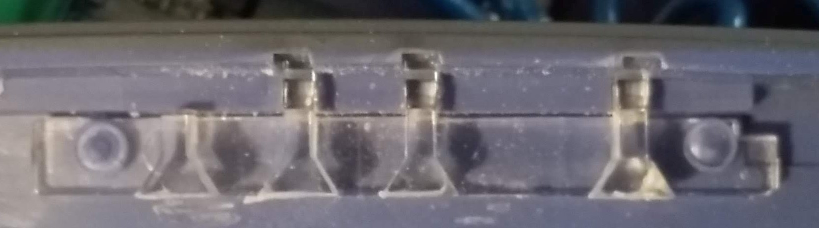
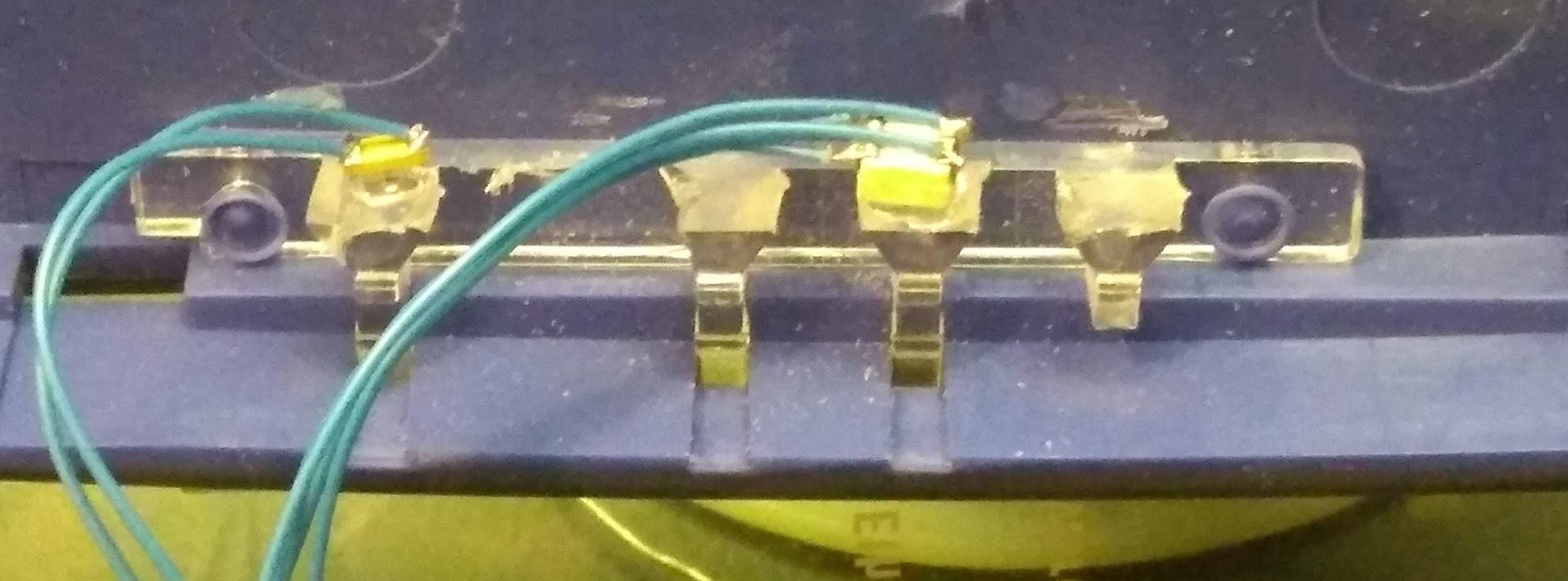
The router case already had light pipes to direct the on board LEDs out the front. They were long and curved, and I had cut them off in order to fit the amplifier board in the case. I used a small sanding disk to sand the edge flat and then glued the LEDs down to the surface which worked great.
Finished
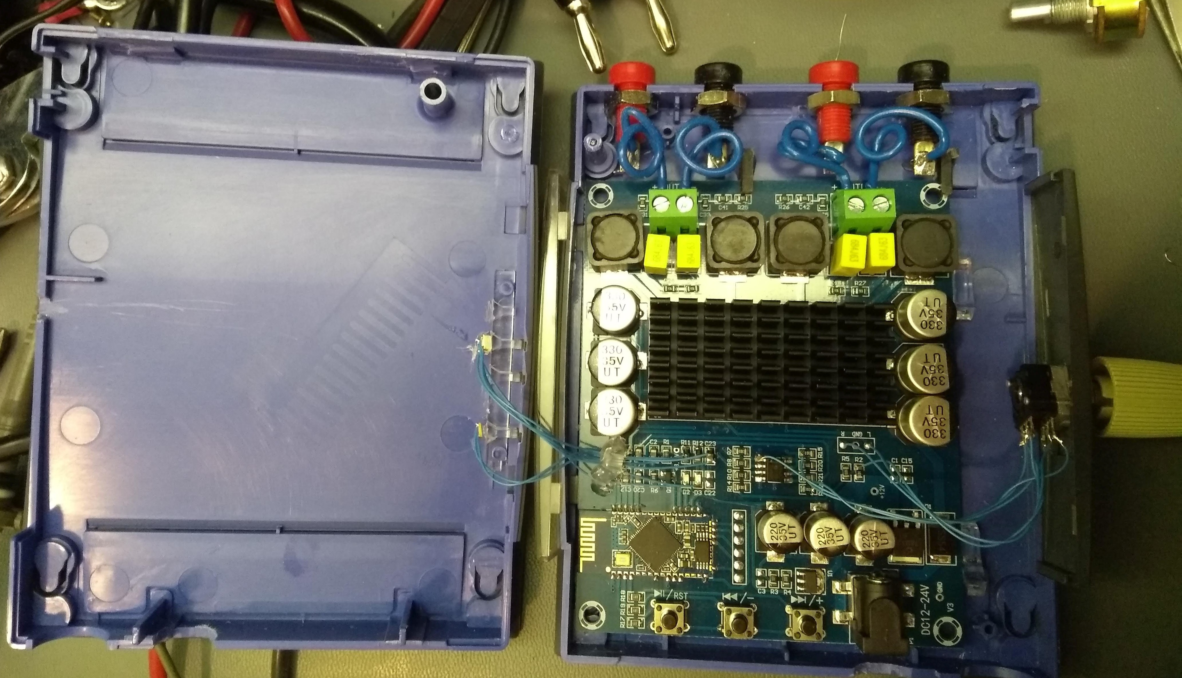
Here is all the modifications done and everything installed
Discussions
Become a Hackaday.io Member
Create an account to leave a comment. Already have an account? Log In.