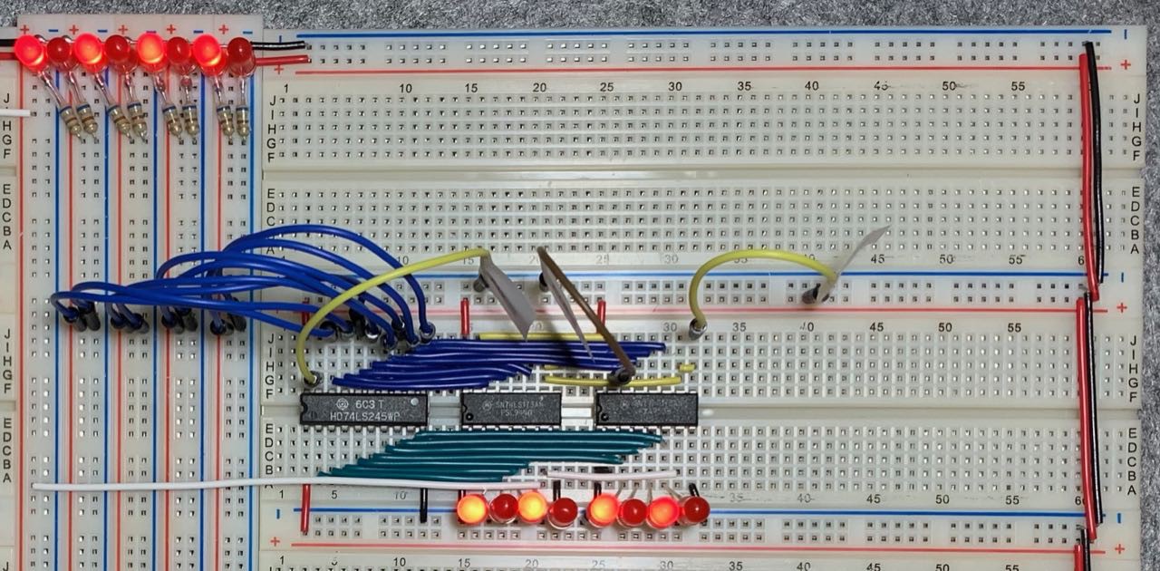
I haven't been feeling well today, but I did manage to get register A re-wired on the new breadboards. The new wire (green) is much easier to work with than the purple coated wire I had been using previously. I am reasonably happy with the results here, but I could probably have done the blue data bus wiring a little neater if I tried.. 8^)

 Amos
Amos
Discussions
Become a Hackaday.io Member
Create an account to leave a comment. Already have an account? Log In.
And just like that, register B is now complete too. (No pics this time - it look identical to register A above, just with different labels on the control wires. 8^P)
I'm going to take a break from this project for a little while so I can catch up on some other projects I have under way. The next task will be to implement the ALU. Plus I will need to do something about making the breadboards a bit more rigid - because there are no dovetail clips holding the data bus to the modules on either side, things can slide out of place too easily. I will probably just use a couple of dots of superglue to hold everything together. When everything is firmly connected and I eliminate the slippage, I can wire the modules into the data bus properly instead of using the jumper wires.
Thinking about the wiring: I am not entirely happy about the layout. Trying to fit eight wires into three rows is a bit of a pain, and things are only going to get more painful when I wire up the registers to the ALU. To quote Uncle Bob "There must be a better way!" I think I will experiment with short loops for some of these chip to chip mini-busses. When I was first exploring this design I actually used 4- and 8-pin Dupont-style connectors, but the ribbon cable got a bit messy, but maybe short loops of solid core wire might work (and look neater)? I'll give it a try in a day or two and see how it goes...
Are you sure? yes | no