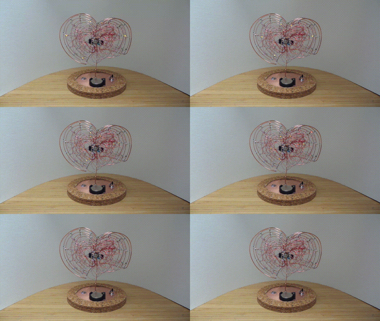
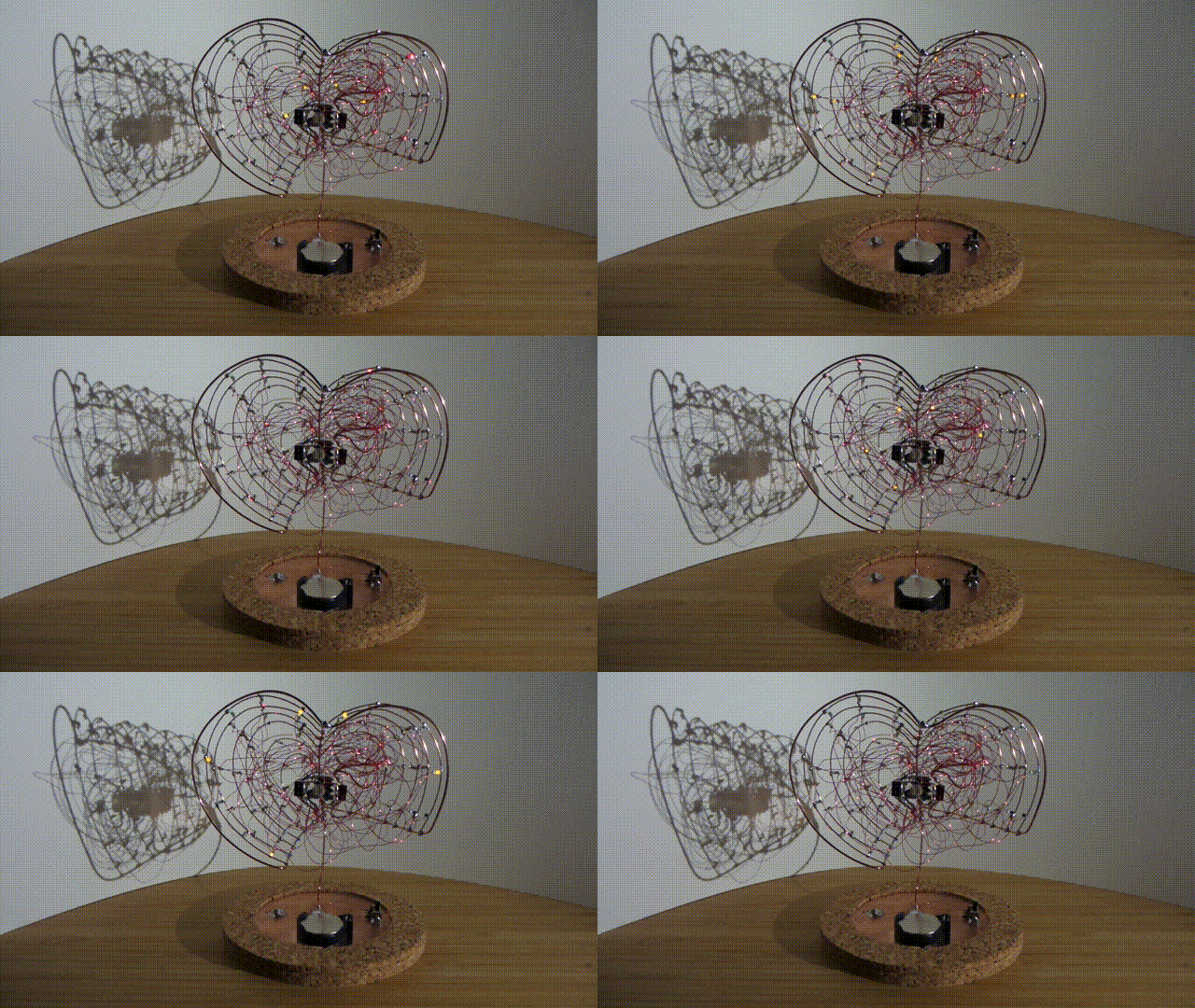
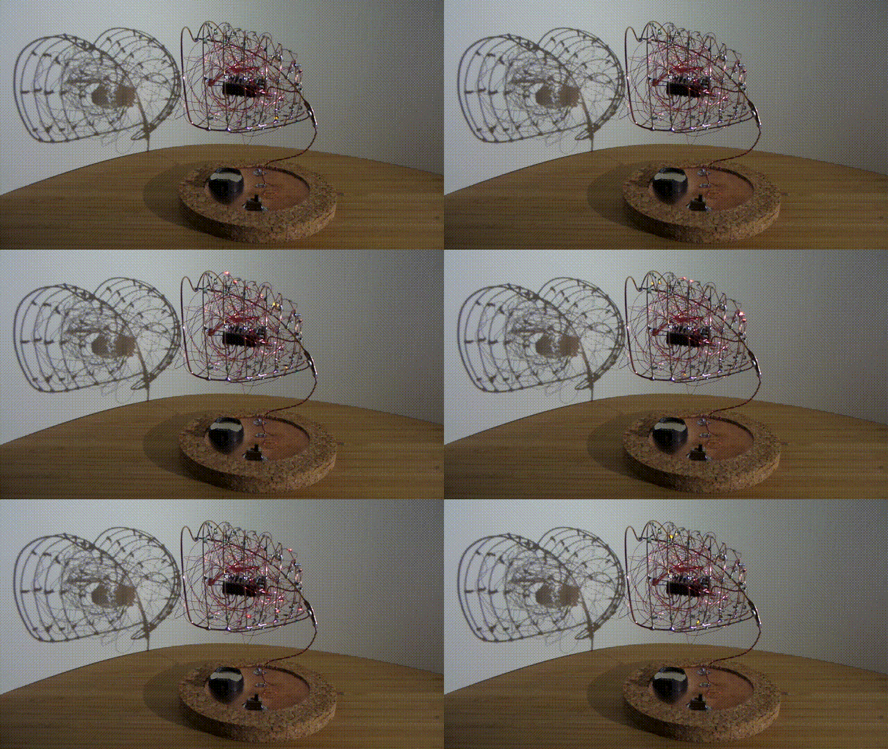
All the details of the design and how it works are available in the project's GitHub Repo (see the catalog for my other projects).

The skeleton is made with 0.9mm and 0.55mm copper wire. The idea started as a very rough sketch in a notebook, and improvised in 3D by eye.
At first I was thinking of embedding a microprocessor in the project, but eventually decided to keep it old school with a classic 555 timer and CD4017 decade counter combo.
The base is made from some copper PCB stock and 3 cork coasters. It includes a CR2032 coin cell holder, switch and some external power connector pins.
The circuit is a very simple variation of the classic CD4017 counter with a 555 astable clock source. A light-dependent resistor provides some frequency variation depending on available light. The LDR ranges from around 1kΩ when in light to 10kΩ when in darkness, corresponding to a clock frequency range of perhaps 6.5Hz to 34Hz. The two CD4017 counters are wired in parallel - mainly for symmetry in the final design.
Up to 5 LEDs are attached to each counter output (not all pins are actually used in my final build). Enamelled 0.2mm magnet/winding wire is used for connecting the the LEDs, which are grounded on the main skeleton. I kept the internal wiring messy to provide some chaotic volume to the "pollen" while still maintaining transparency.
Demonstration
This is a quick capture of the view from the front, where a distinct pattern in the LEDs is apparent:

When viewed from other angles, the LEDs dissemble into a chaotic display:

I'd like to do a better 360 view if I can rig up a turntable photo stage. For now, a very manual tour is in this youtube clip:
 Paul Gallagher


Fantastic! Very cool. Nicely done