 Wassim
Concept
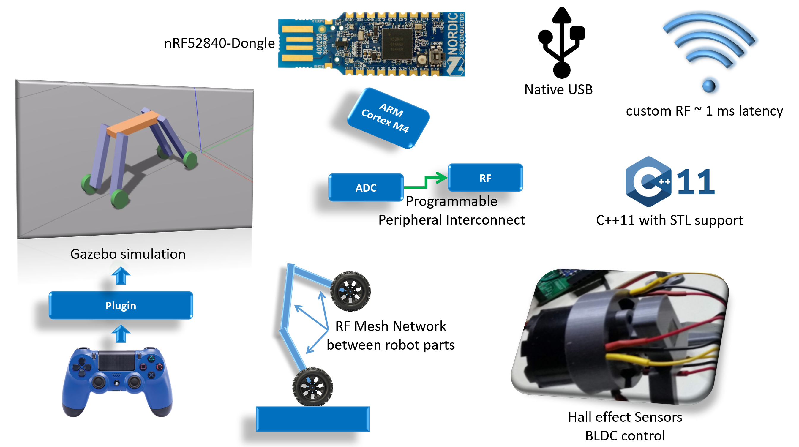
- A gazebo simulation approximates the robot's physics and allows the user to control it with a joystick to have a feeling of the robot's power depending on the weight and motors power.
- nRF52840 Allows high throughput log with native usb uspport.
- A custom RF protocol allows 1 ms order of magnitude for mesh network communication between the different robots part.
- The Programmable peripheral Interconnect feature of the nRF family is leveraged to increase real time responsiveness of events. This is like having a small FPGA interconnect inside of a powerful micro controller.
- C++ drivers wrappers and Standard library support.
Requirements
- The robot shall have a body and 4 limbs.
- Each limb shall have a motorized joint connecting it to the body.
- Each limb shall have a motorized wheel.
- In flat mode, the robot shall be able to move like a tank.
- The robot shall be able to go from flat mode to standing mode.
- The robot shall be able to keep balance and move in standing mode.
- All articulations shall be reversible, to allow force control loop (smooth interactive reaction).
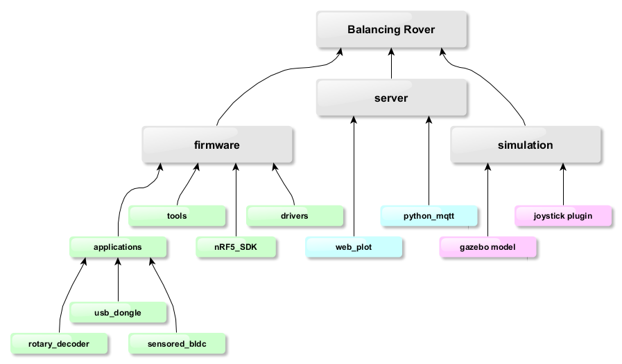
Github repo structure
https://github.com/Roblibs/balancing_rover.git
(includes 1 level of submodules)
Shared development on google drive
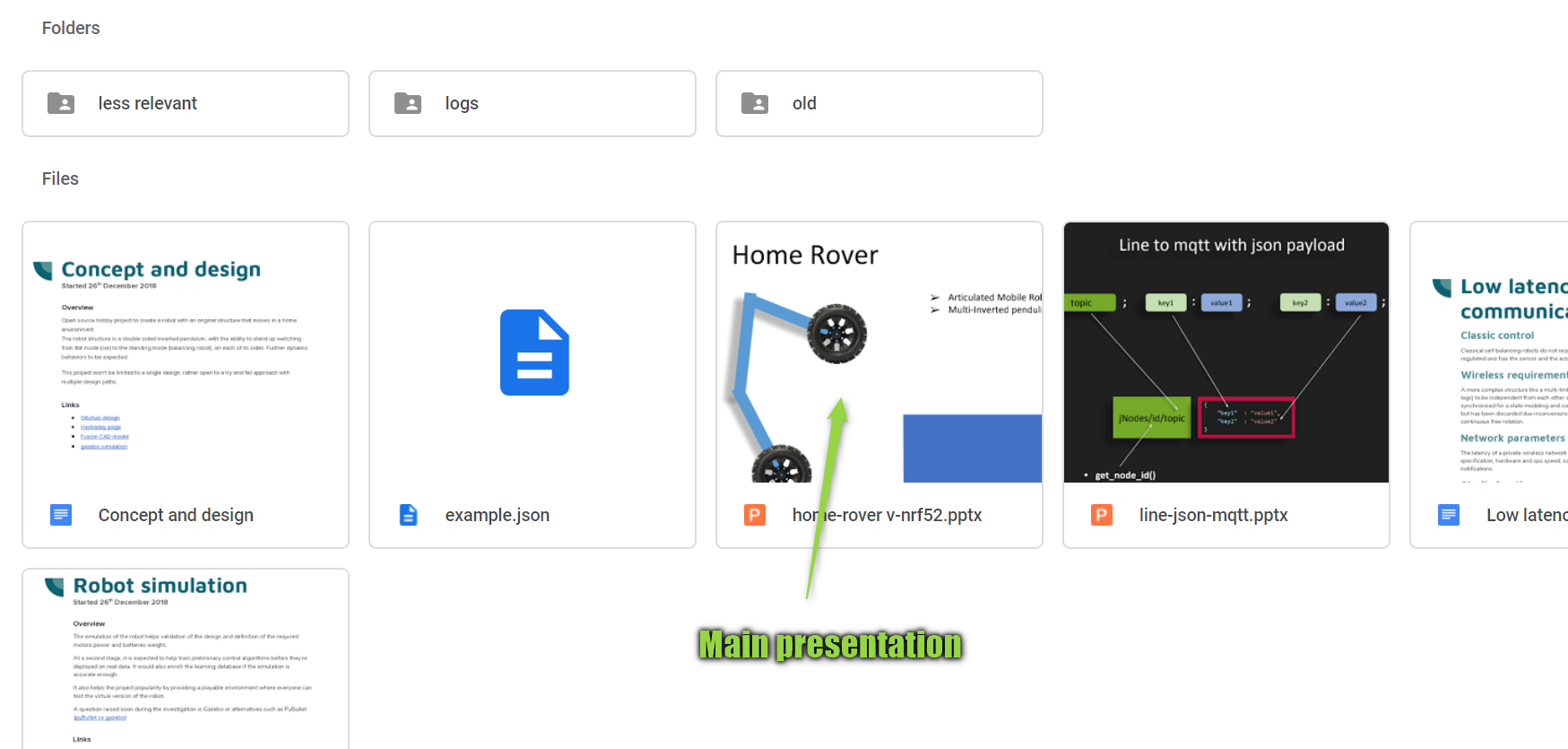
- Google drive gzrover project root directory : the specification, design and development details of this project will be shared live on google docs.
Shared notes on OneNote
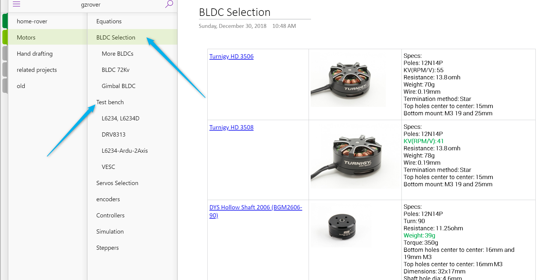
- notes : draft packing of all notes related to selections, development links, ongoing progress,...
Video of the gazebo simulation
Construction thoughts
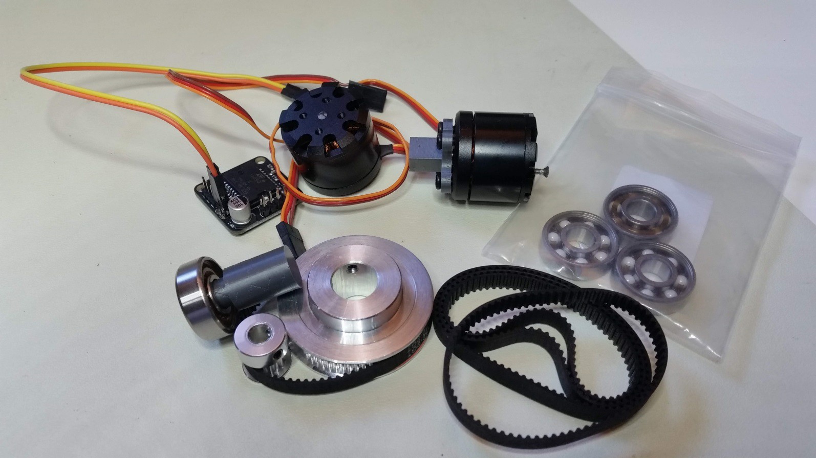
The construction details are not set yet, thoughts go around BLDCs and pulleys.
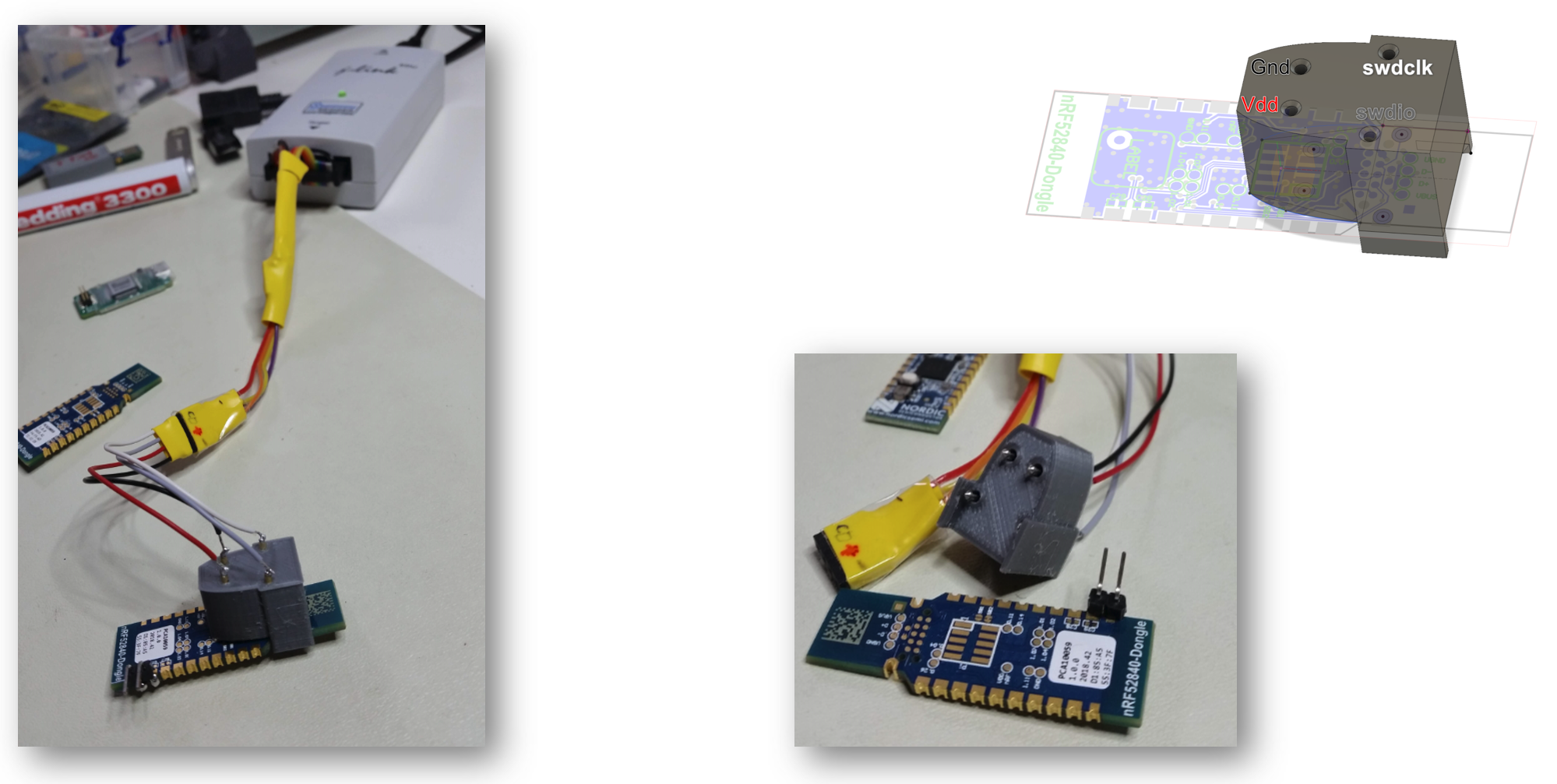
nRF52840-dongle
jtag pogo adapter
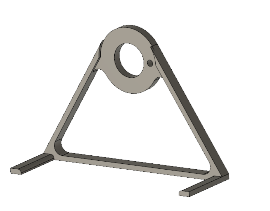
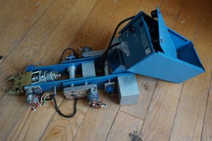
BLDC Test bench
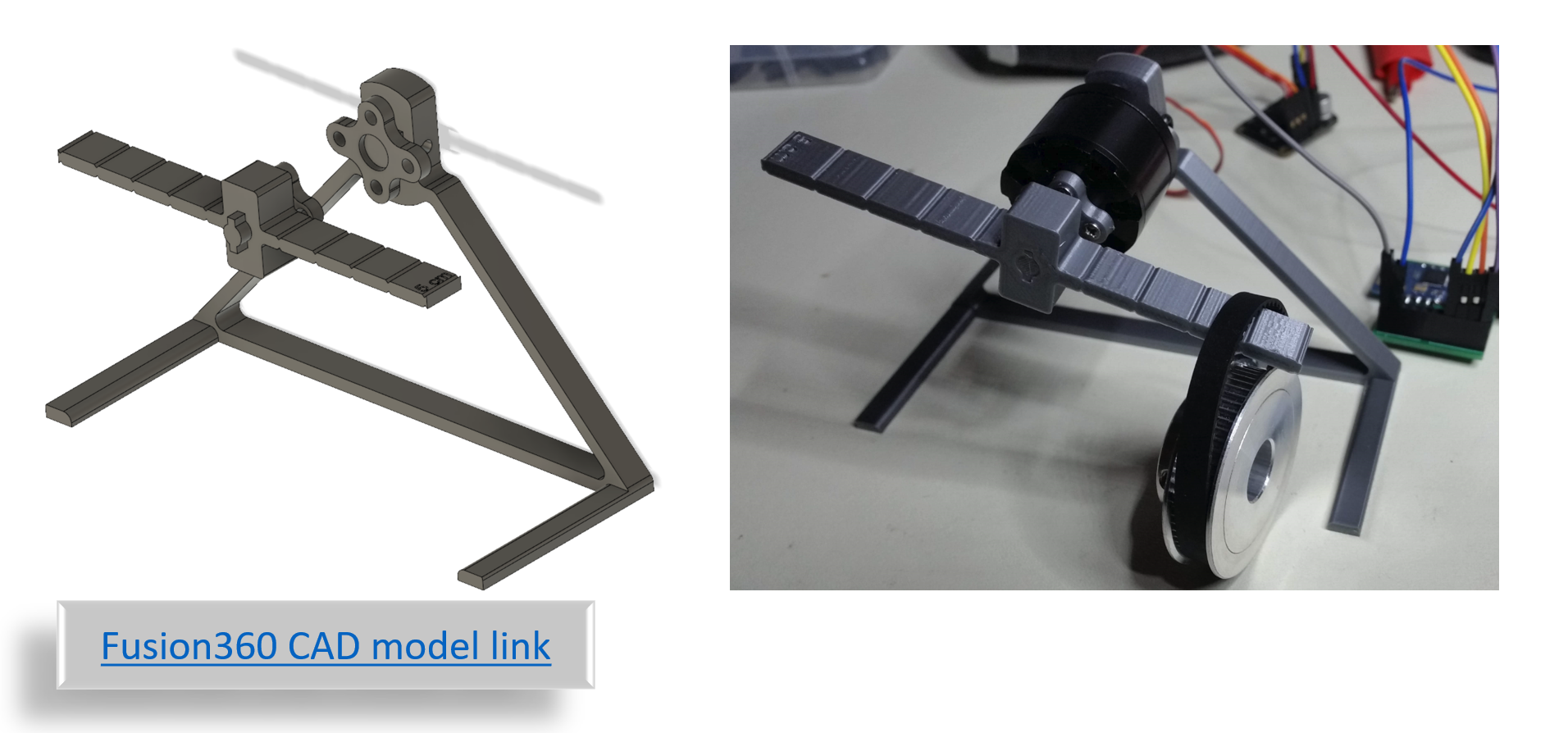
- Test bench CAD model, to be used for static load measures
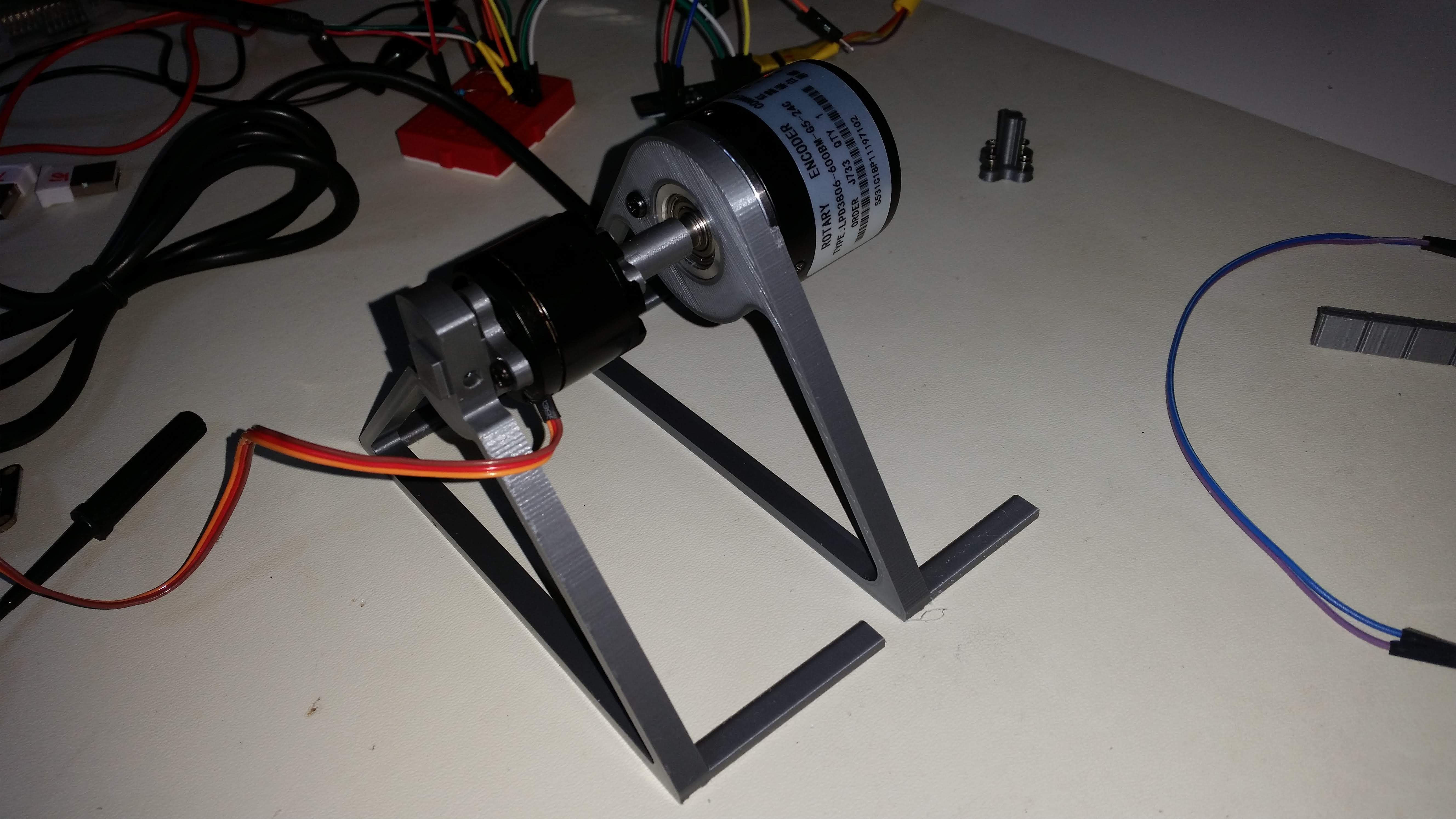
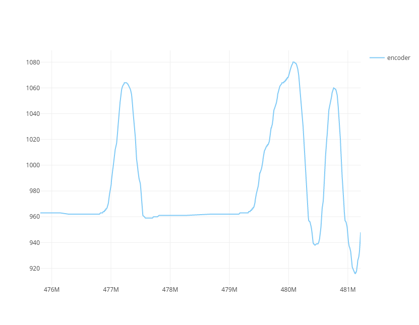
Encoder for testing purpose
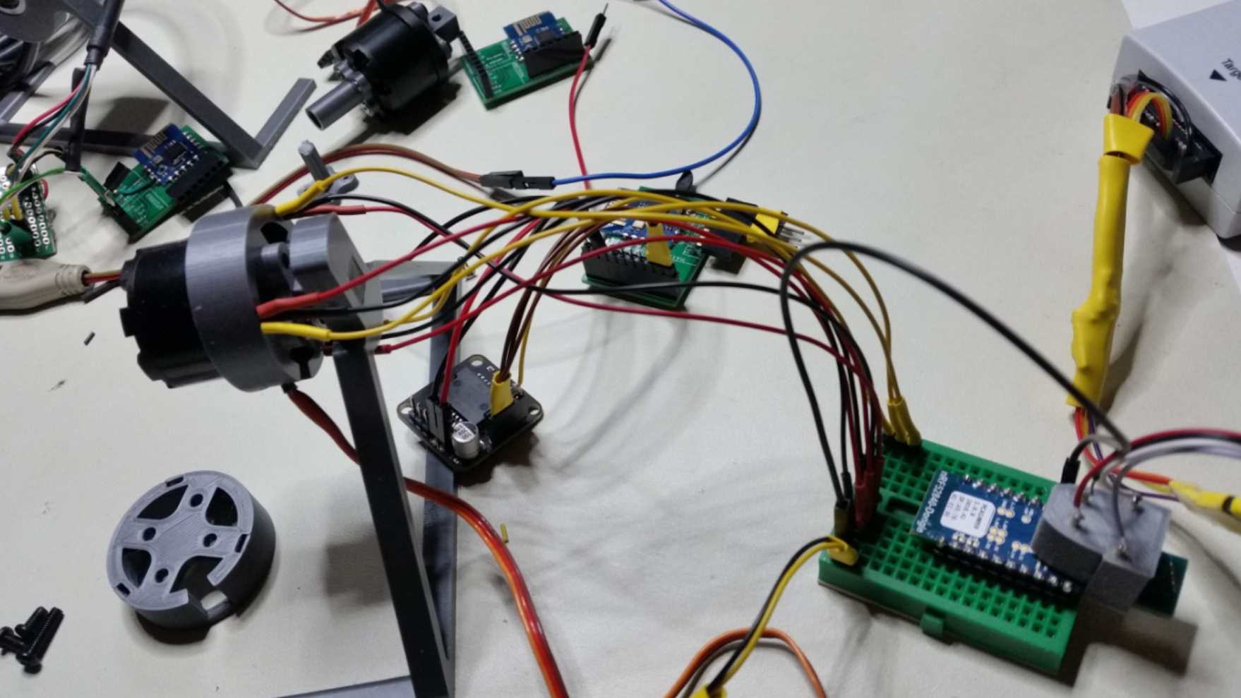
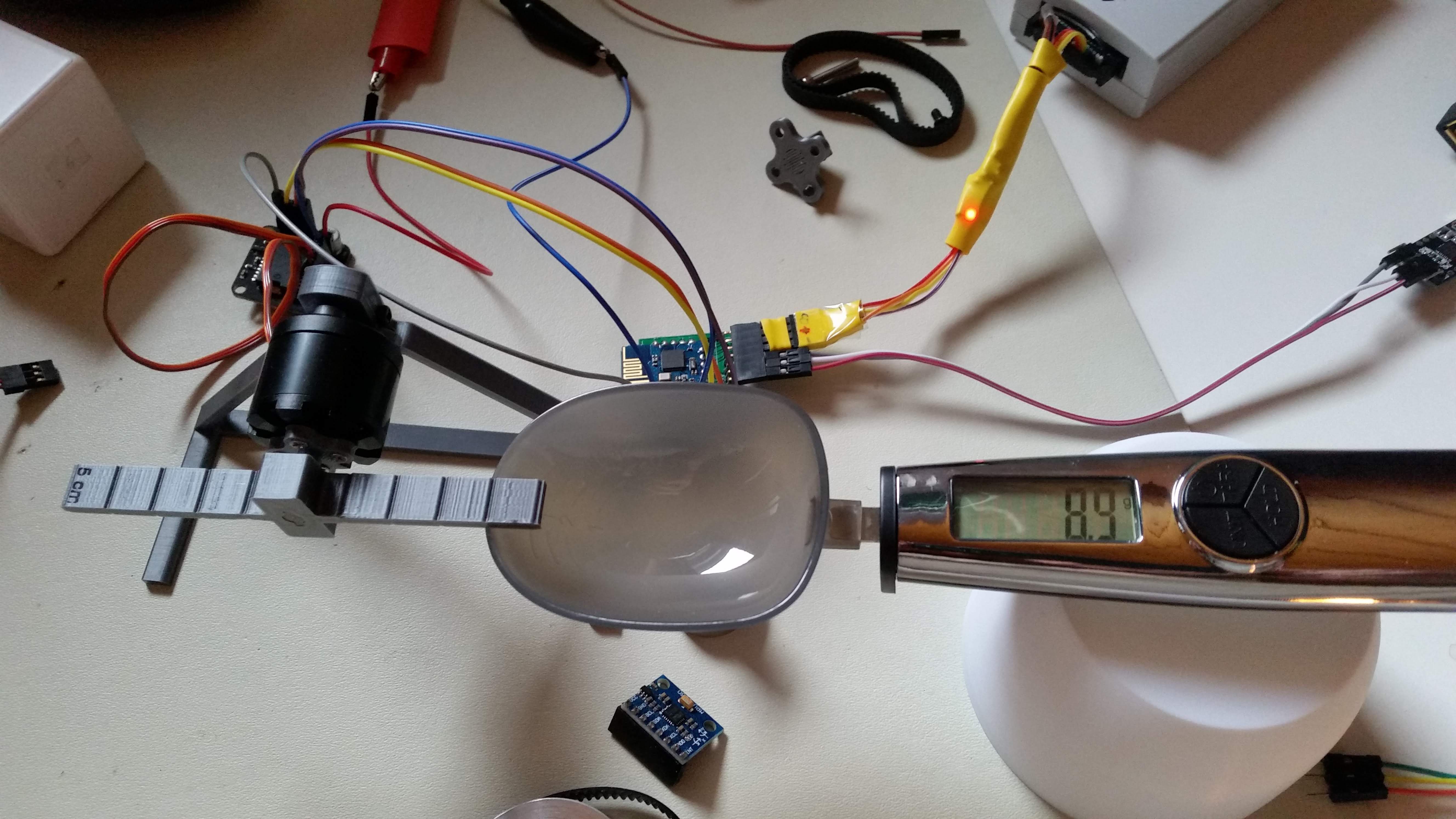
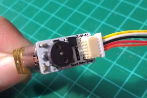
![]() Experiments with sensored motor
Experiments with sensored motor
 Experiments with sensored motor
I used AH3503 so far which are 4.5 V min rated but under powered with 3.3, in the meantime I ordered some OH49E that are 2.3 - 10 V so should be fine with 3.3 V within the specs.
nRF52 SDK with nrfx drivers, c++11 and standard library
This example application is somehow a step forward, as I finally managed to :
- use the latest nrfx API and get rid of the clumsy nrf_drv_ wrapper usage (at least for bldc.cpp as example)
- get rid of the headache of sdk_config.h (at least for bldc and pwm config)
- wrap usage in c++ so that as example the the bldc_c takes the config params in the constructor for a dead simple Arduino like c++ class usage.
- add support for the standard library std::string and others after quite a search to find that I had to link the lib (-lstdc++) in the linker flag, as simple as that (see makefiel)
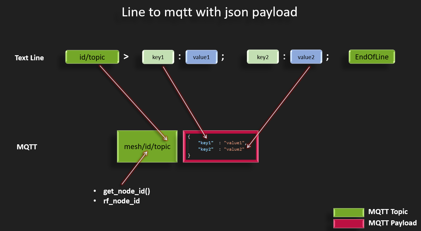
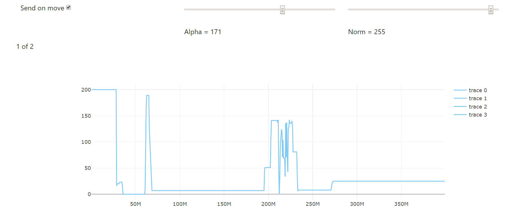
Line to mqtt with json payload
Only after all the previous listed enhancements, it because easy to parse a line text protocol. That allows to get rid of binary traslation of packets as this text like is jsonish in a way that it's a key:value structure but simple as it is unidimensional.
 Danny FR
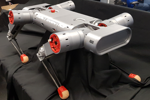
 Charles Galambos
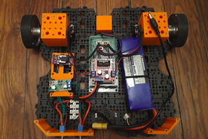
 matop
matop