Mounting the circuit
Let's start mounting the circuit. Always unplug the USB cable out of your computer for safety reasons. First, place the ultrasonic sensor horizontally onto the breadboard. Behind, the sensor, insert the 4 jumper wires into the pins. Connect the wire that is behind the VCC (+)on the sensor into 5v (+5 volts)on the Arduino. Next, connect the wire that is behind the TRIG (signal)pin on the sensor into D8 (digital pin 8). Then, connect the wire behind ECHO on the sensor to D7 (digital pin 7). Finally connect GND (-) on the sensor to GND(-) on the Arduino. Use the code below and open the serial monitor to 9600 bauds. You should see the results coming in through the sensor and onto serial monitor after uploading the code. Use the code below:
Arduino LED Project Code
int ledpin1 = 3;
int ledpin2 = 4;

void setup() {
  digitalWrite(ledpin1, HIGH);
  digitalWrite(ledpin2, HIGH);
  delay(200);
  digitalWrite(ledpin1, LOW);
  digitalWrite(ledpin2, LOW);
  delay(200);
}

void loop() {
  digitalWrite(ledpin1, HIGH);
  delay(100);
  digitalWrite(ledpin2, HIGH);
  digitalWrite(ledpin1, LOW);
  delay(100);
  digitalWrite(ledpin2, LOW);
}
About the code
This piece of code is very easy to understand as it's for absolute beginners. The code starts off by defining the two variables for each of the LEDs to pins 3 and 4. The next set of code describes the initial process of setting up the main program, this set of code is called the void setup. First, one LED is on, followed by the other, a delay of 200 milliseconds occurs, then both LEDs are off followed by another delay of 200 milliseconds. The second code lines are called the void loop, they go on forever, until power is not given. It starts off with one LED going on, waiting for 100 milliseconds, then another LED is set to HIGH. After, the first LED is turned off completely followed by another delay of 100 milliseconds before finishing off with the second LED set to LOW. There you have it, the full project complete.
Enjoy! Contact us for any inquiries!


 Hulk
Hulk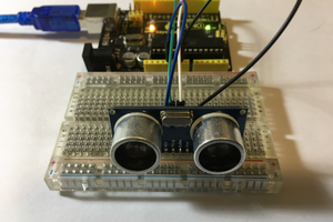
Actually you missed the far more interesting offer from your sponsor, up to 10 100x100 PCBs for shipping only.
I don't need an infrared thermometer. I'll know I have a fever when the cat jumps onto my head. 😉