 Nathan Brown
First I was inspired by other Pikon projects:
https://incoherency.co.uk/blog/stories/pikon-telescope-hardware.html
&
http://pikon.patrickaalto.com/pikonblog.html
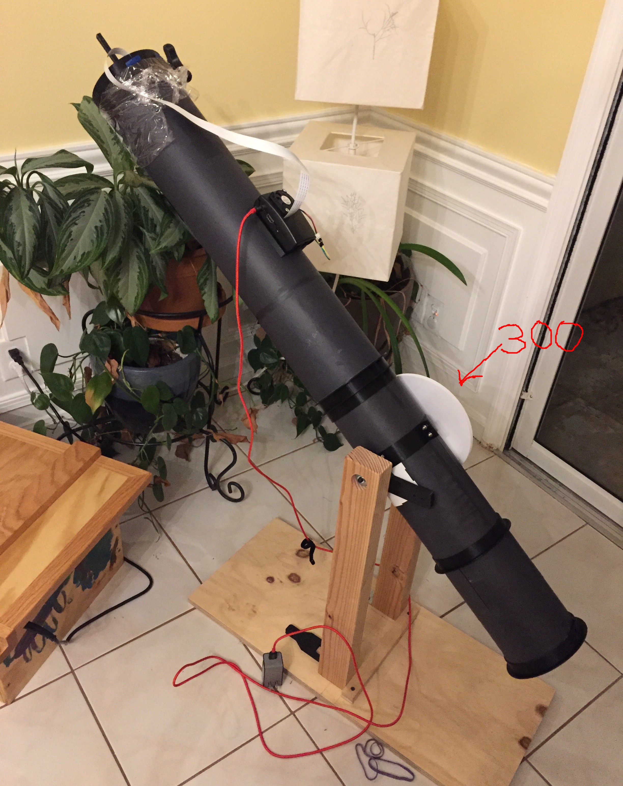
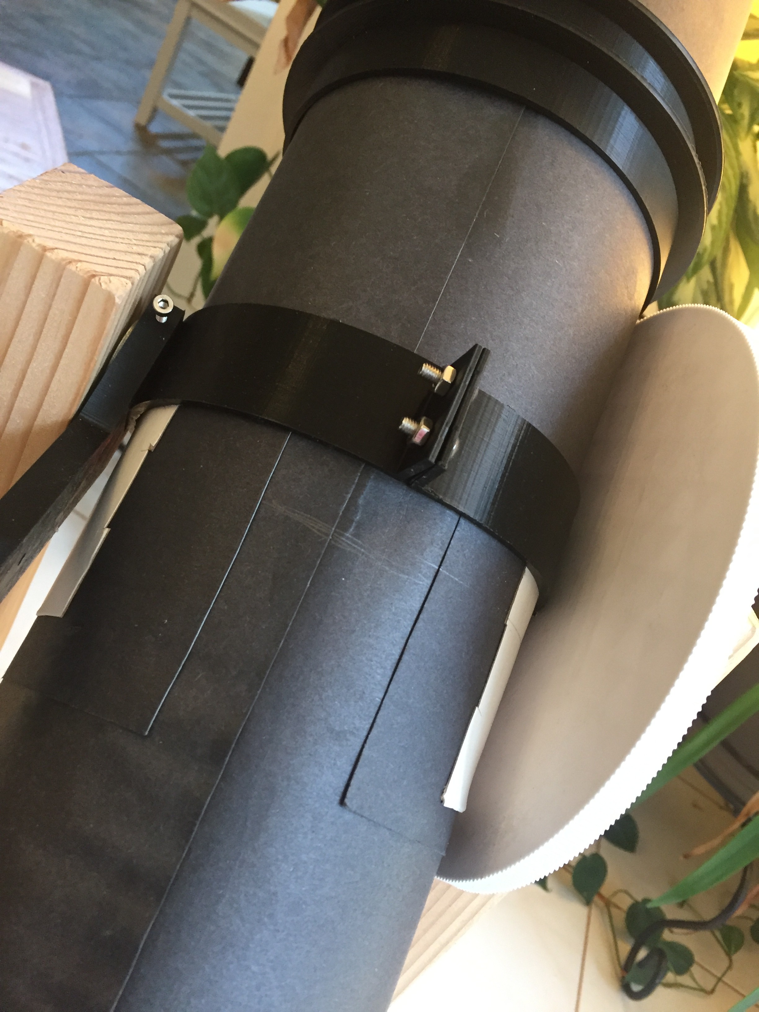
..and like most strikes of inspiration I went straight to amazon and bought stuff. Also like most of my frenzied purchases I had neglected to notice that the mirror I purchased was 1000mm focal (instead of the 500mm per the standard Pikon plans). I also neglected to notice that the Pikon plans call for a metric tube size, which turns out to be quite difficult to source here in the US. Naturally by this point I had already printed all the parts and worse of all... I committed the cardinal sin. I told my wife and kinds that I was building a telescope! A full eight months later I finally had a telescope.
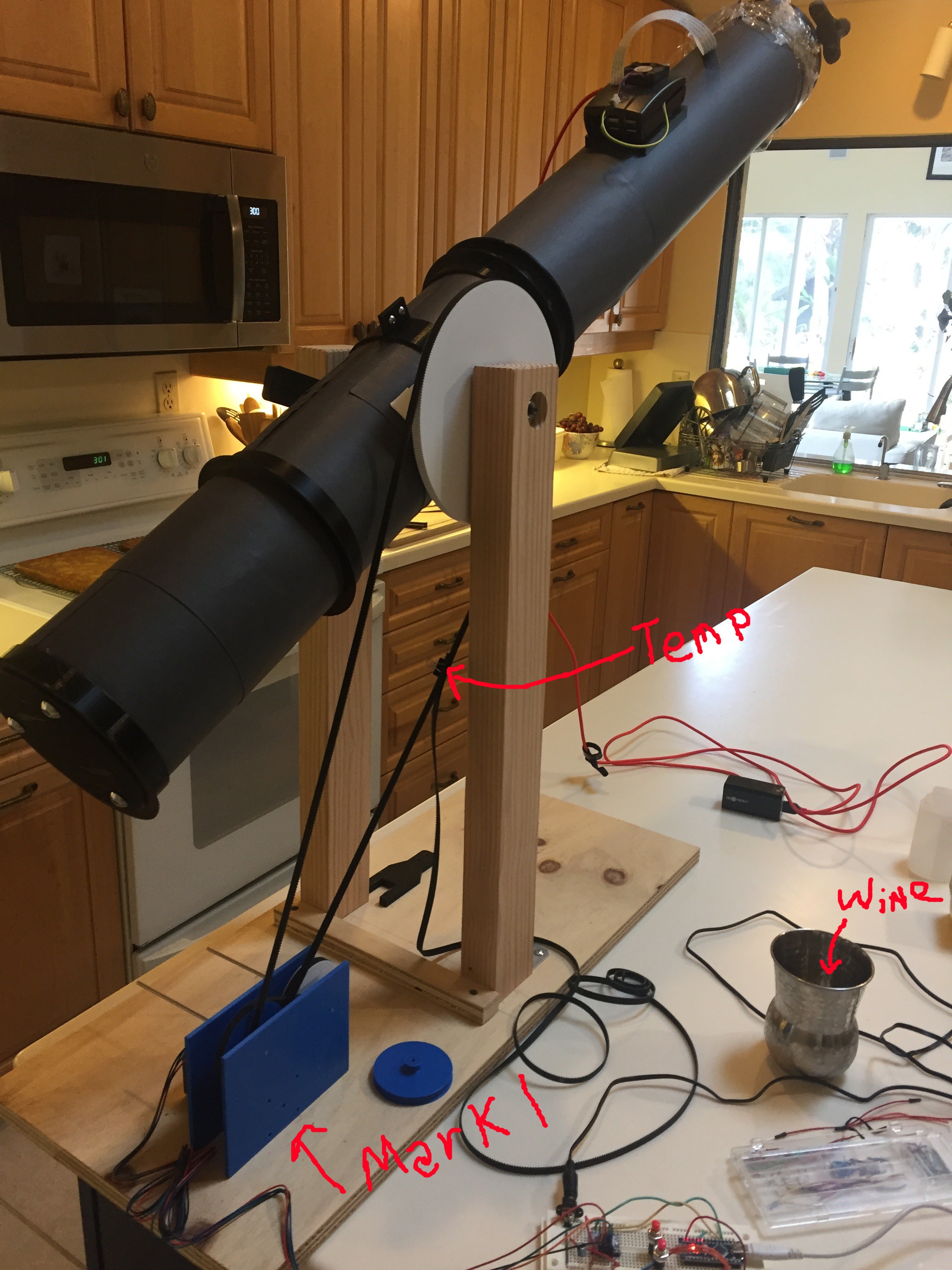
The first set of instructions is mostly about building the telescope itself out of poster board. However, this project has quickly morphed into a motion control system about how to control the telescope.
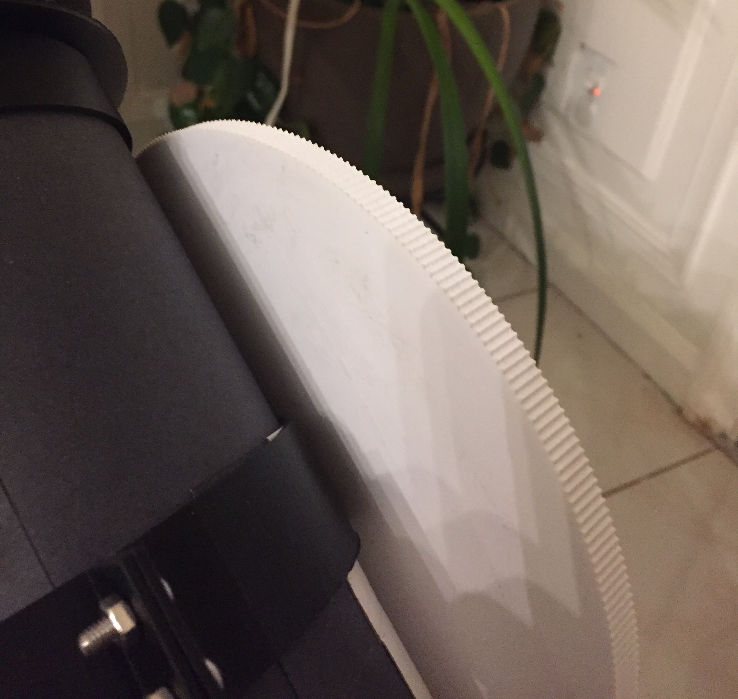
Special thanks to the people who made the OpenSCAD pulleys and gears:https://www.thingiverse.com/droftarts/about - Pulleyshttps://www.thingiverse.com/janssen86/about - Focus Gears

 Douglas Miller
 Kenneth Zaborny
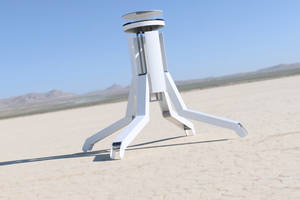
 Paul Crouch
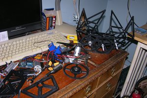
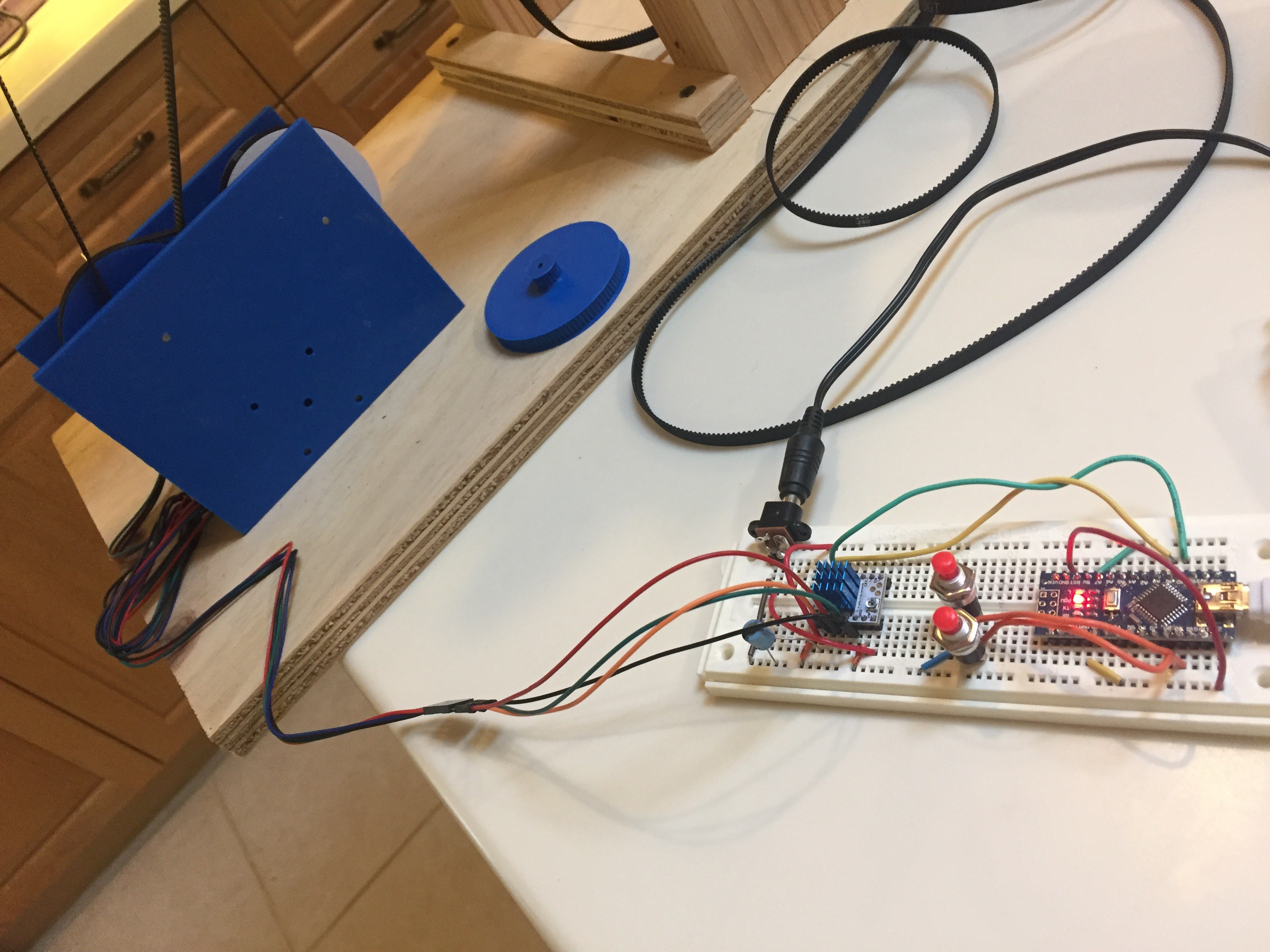
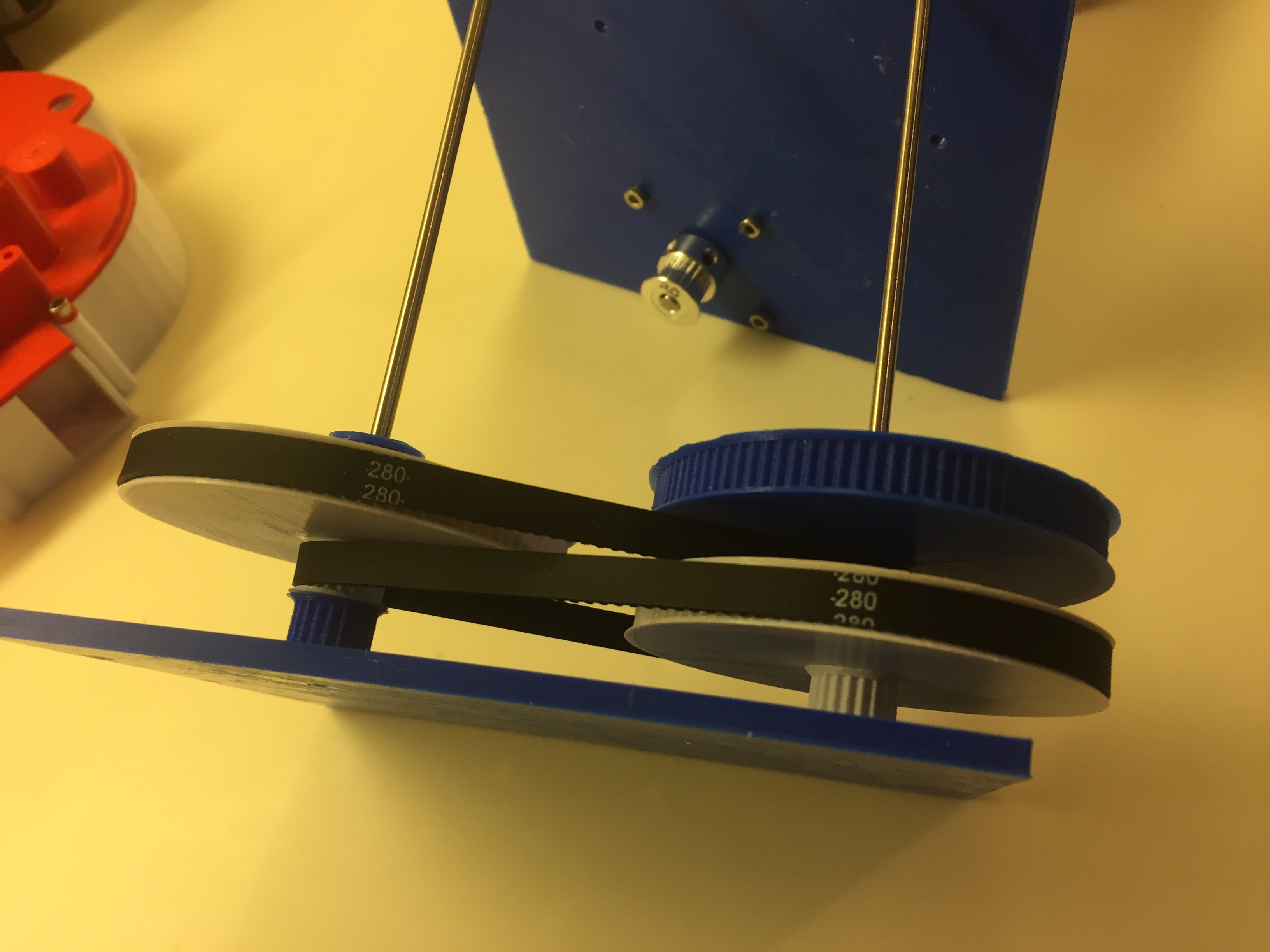
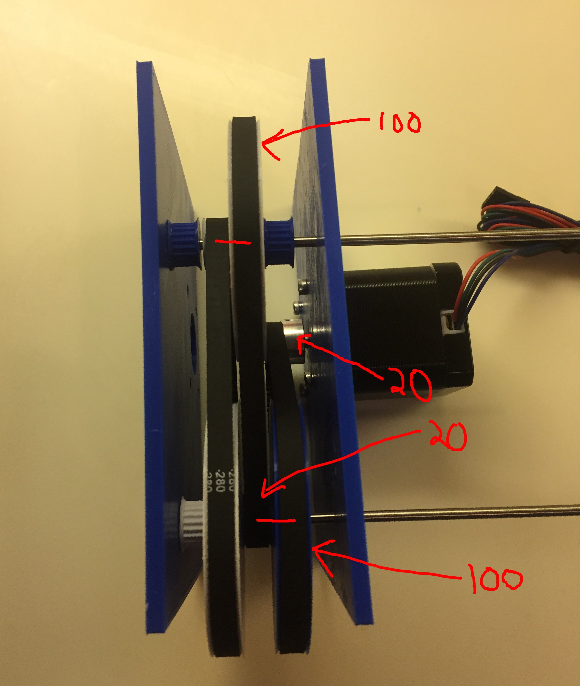
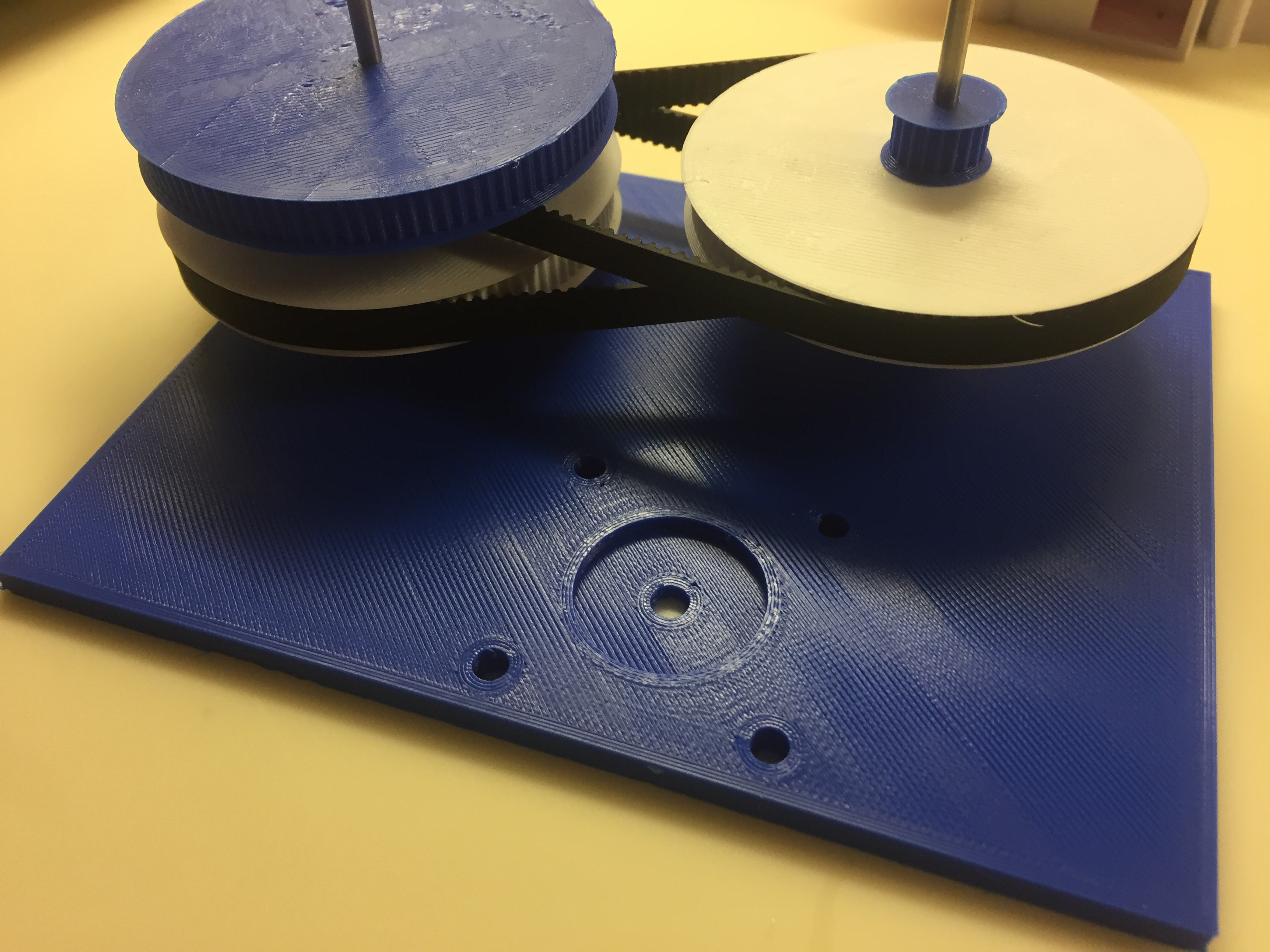
cogs are all 3D Printed. I'll be posting them shortly. I'm still finishing up the reduction box. I'll post the links to the belts right now. I got the threaded rod at my local hardware store.
I'm still in the processes of catching up this project page with all things I have done thus far so more is coming.