 Ted Yapo
I figured for a first try, I'd use a $6 ADCMP606 CML-output comparator. It's not the fastest available, with leisurely 160 ps typical Tr/Tf, and 1.2 ns minimum pulse width. There are faster ones available, like the $70 HMC874, with 24 ps rise and 15 ps fall times and 60 ps minimum pulse width. I wanted to get some experience with these things before plunking down that much cash.
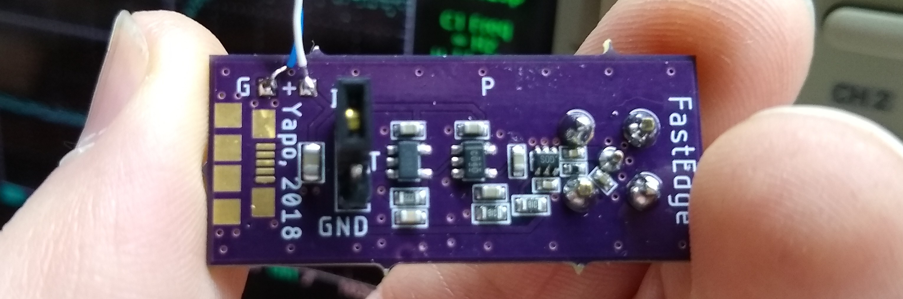
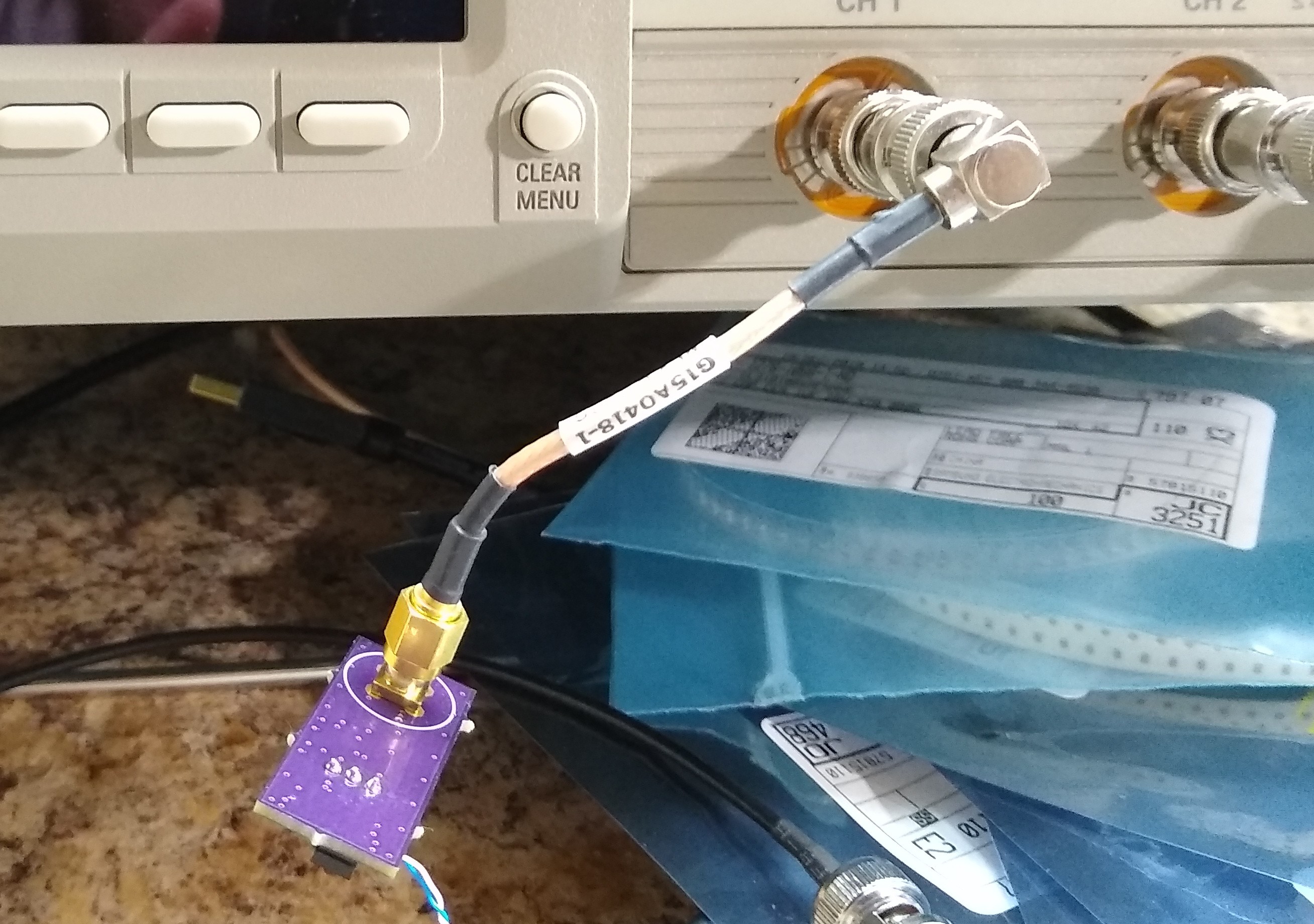
I designed a quick circuit using a 74LVC1G14 Schmitt-trigger inverter as an oscillator at about 500 kHz. The oscillator drives a 74LVC1G04 as a buffer than then drives the + input of the ADCMP606 comparator. The - input of the comparator is held at mid-supply with a bypassed voltage divider. The output is AC-coupled to an SMA connector. I made a mistake on the PCB and used the wrong footprint - it was supposed to be a PCB-mount male BNC so the board could be connected right to a 50-ohm terminated oscilloscope with no cable. More on this below.
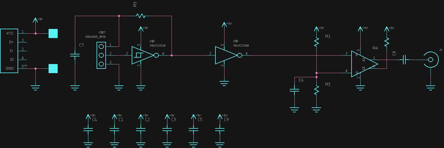
There's a jumper to select free-running or triggered pulses. With the jumper removed, two of the pins are the trigger input and ground. There's a USB connector for power, but I didn't populate it.
There's no added hysteresis in the circuit - If I make another one, I'll probably add some, since there is a little oscillation on the falling edge - I suspect ground bounce.
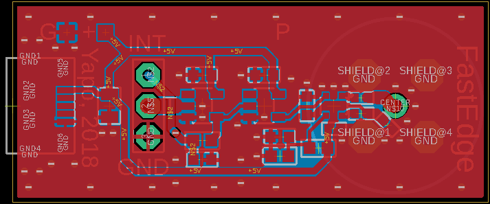
I tried to keep all the high-speed stuff small and near the connector in the PCB layout, using 0402 parts where it counts around the SC-70 comparator. I didn't have any large value 0402 capacitors, so the output pulses don't look square - the 10 nF cap and the 50-ohm impedance make a nice high-pass filter. When I get some, I'll fix it.
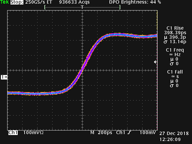
So, how does it work? I measured 400 ps rise time with a 1 GHz scope. I did have a section of coax in between the pulser and the scope, which could be increasing transition times through dispersion - I have some adapters on order so I can connect it without any cable and see if the measurement changes.
This measurement is also problematic because it's (probably) very close to the rise time of the scope itself. So, I may be measuring the scope more than the pulse.
The bandwidth of the scope and its rise time are inversely related. Tektronix recommends using the equation:
for modern real-time digital oscilloscopes (older analog scopes are better approximated with a constant of 0.35). Even though the scope (a modded TDS754D) is running in equivalent-time sampling mode at these speeds, it's an interesting data point. This equation would imply a 1.125 GHz bandwidth, which seems reasonable for a 1 GHz scope. I had previously estimated the scope's 3 dB bandwidth at 1.05 GHz. So, the actual pulse edge could be considerably faster, maybe even approaching the typical 160 ps from the comparator's datasheet.
I would be satisfied with this result except for one thing. The ebay seller from whom I bought the oscilloscope had posted an image showing a 284 ps rise time when measured with a 40 ps edge!
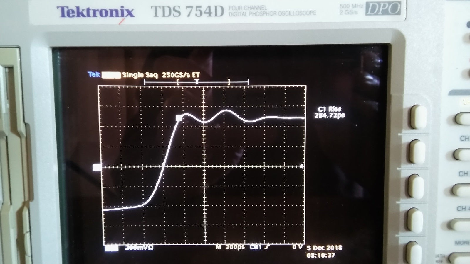
You can estimate the rise time elongation of the scope by applying the formula:
Using this, and assuming the 284 ps rise time is correct, the pulser would be creating 281 ps edges (sqrt(400^2 - 284^2)). That sounds plausible, too, but I have no way of proving it one way or the other at the moment.
It's also possible I may have exhausted my measurement capability on the first shot. If so, it's time to bootstrap some way to measure even faster pulses.
Discussions
Become a Hackaday.io Member
Create an account to leave a comment. Already have an account? Log In.
At the risk of rambling there was a cool circuit I saw a few years ago that was a proposed extension to JTAG for analogue signals. With just 2 comparators per analogue pin repetitive wave forms can be digitised along with the performance of the circuit. Both comparators are fed with saw tooth waveforms, one triggers TCK with the other input being a level that controls the timing, the other sets a level for the input to the boundary scan latch. Really clever minimalist stuff and really high bandwidth. Two fast comparators and a fast latch could probably open up the field of 100ps pulses to people without multighz scopes so long as the pulse source can be made periodic. I worked out 160ps mentioned by Ted in another post to between 3 and 4cm of an electrical pulse.
Are you sure? yes | no
Thanks for this! I'd really like to see that reference, because I have a very similar drawing in my notebook. I wanted to use two comparators also - one to detect a fixed trigger point on the waveform, then another with a variable reference voltage to detect when the signal crossed a variable threshold. The outputs of the comparators feed a TDC7200 time-to-digital converter (http://www.ti.com/product/TDC7200). By scanning through the reference level on the second comparator, you could capture a representation of the waveform.
I picked up a few of the TDC7200's and they're really neat - measuring time differences down to 55 ps (with 35 ps S.D.). It's made for time-of-flight measurement in LiDAR and ultrasonic flowmeters, but ror $2.71 in single quantities, it's just waiting to be hacked into something really interesting. 55 ps is around 8 mm long in a PCB trace!
The problem with the scheme is that you need to find comparators with very low dispersion - most have a propagation delay that depends on the amount of overdrive, so they'll flip at different times depending on the waveform shape near the trigger level. They make very low-dispersion types (like down to 50 ps), but they seem to be expensive. Garden-variety fast comparators can have horrendous dispersion.
I also considered a two-comparator scheme with the comparators simply adjusted to 10% and 90% of the waveform amplitude (or 20% and 80% as you desire). Now, measuring the delay between the two comparator outputs gives you the rise time. Again, I'd use a commercial time-to-digital converter.
Now, you've got me rambling :-)
Are you sure? yes | no
Microchip bought Micrel a while back. They have a fast clock distribution product line.
https://www.microchip.com/design-centers/clock-and-timing/clock-and-data-distribution
>Up to 16 input Max, PECL/LVPECL/CML/LVDS, Up to 7.0 GHz clock rate & 10.7 Gbps data rate
A MUX can be used as a hardwired lookup table to implement combination logic if you get desperate enough.
Are you sure? yes | no
Yes! I have a PECL clock distribution part in a design I'm working on now. The awesome thing is that they have very low skew between outputs, so you can create a sort pulse by using a longer transmission line on one output, then combining the two in a PECL AND/NAND. The key being that the pulse width is determined by the difference in transmission line lengths, which doesn't vary much with temperature and voltage - and, you can make decent lines with diff. pairs on a PCB.
Are you sure? yes | no
"I may be measuring the scope more than the pulse."
yup :-D
Are you sure? yes | no
"We're going to need a bigger scope."
Are you sure? yes | no
but then you need a bigger pulse to measure it !
Are you sure? yes | no
https://cdn.hackaday.io/files/470302012131520/2pxvlv.jpg
Are you sure? yes | no