 Ted Yapo
I have often used a Z0 (resistive) probe in the past, especially for fast digital logic. This consists of nothing more than a resistor at the end of a piece of coax. Combined with the 50-Ohm termination inside a high-speed oscilloscope, this creates a voltage divider that reduces the loading on the circuit under test. I finally got around to testing this type of probe with the new scope.
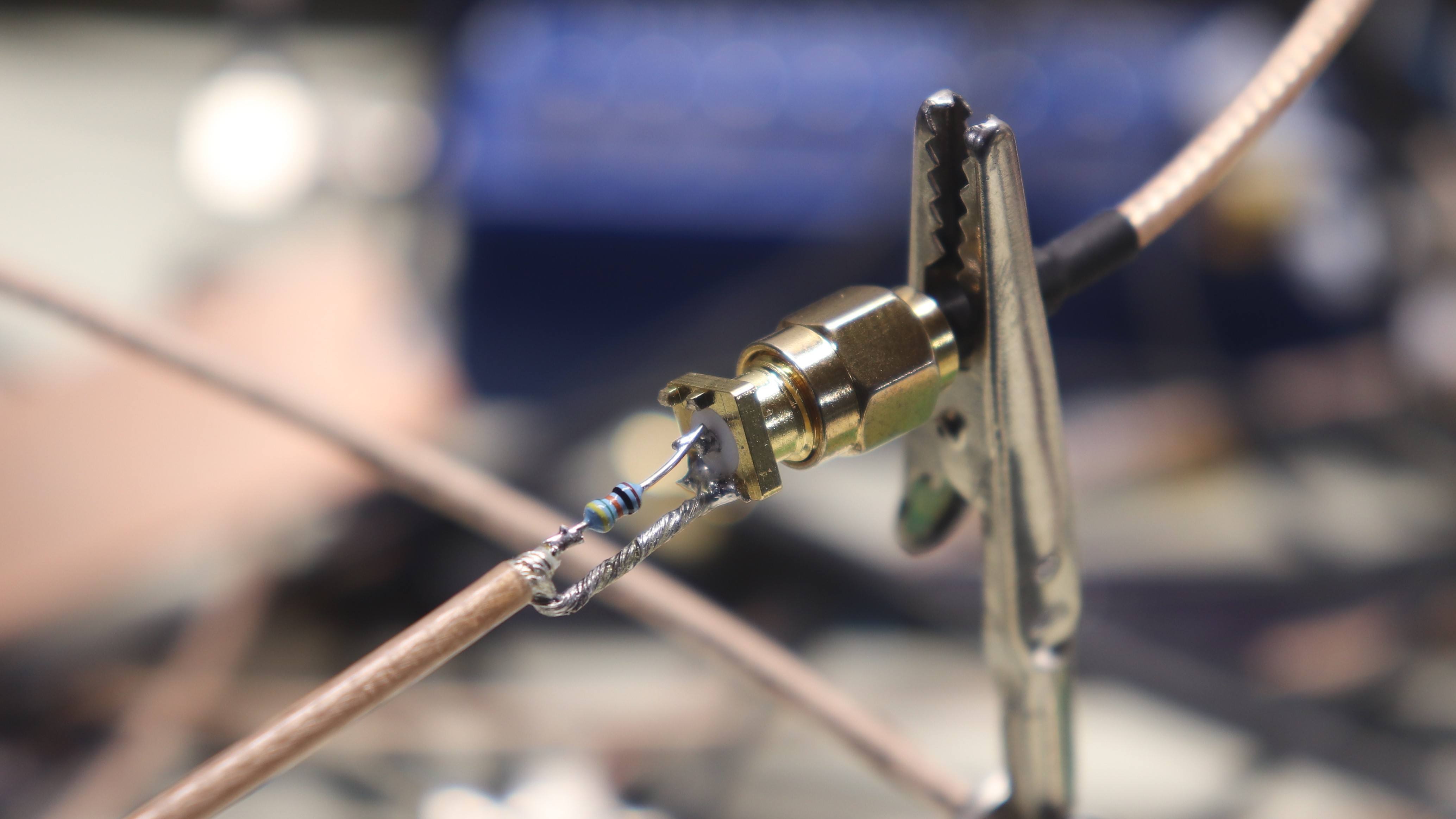
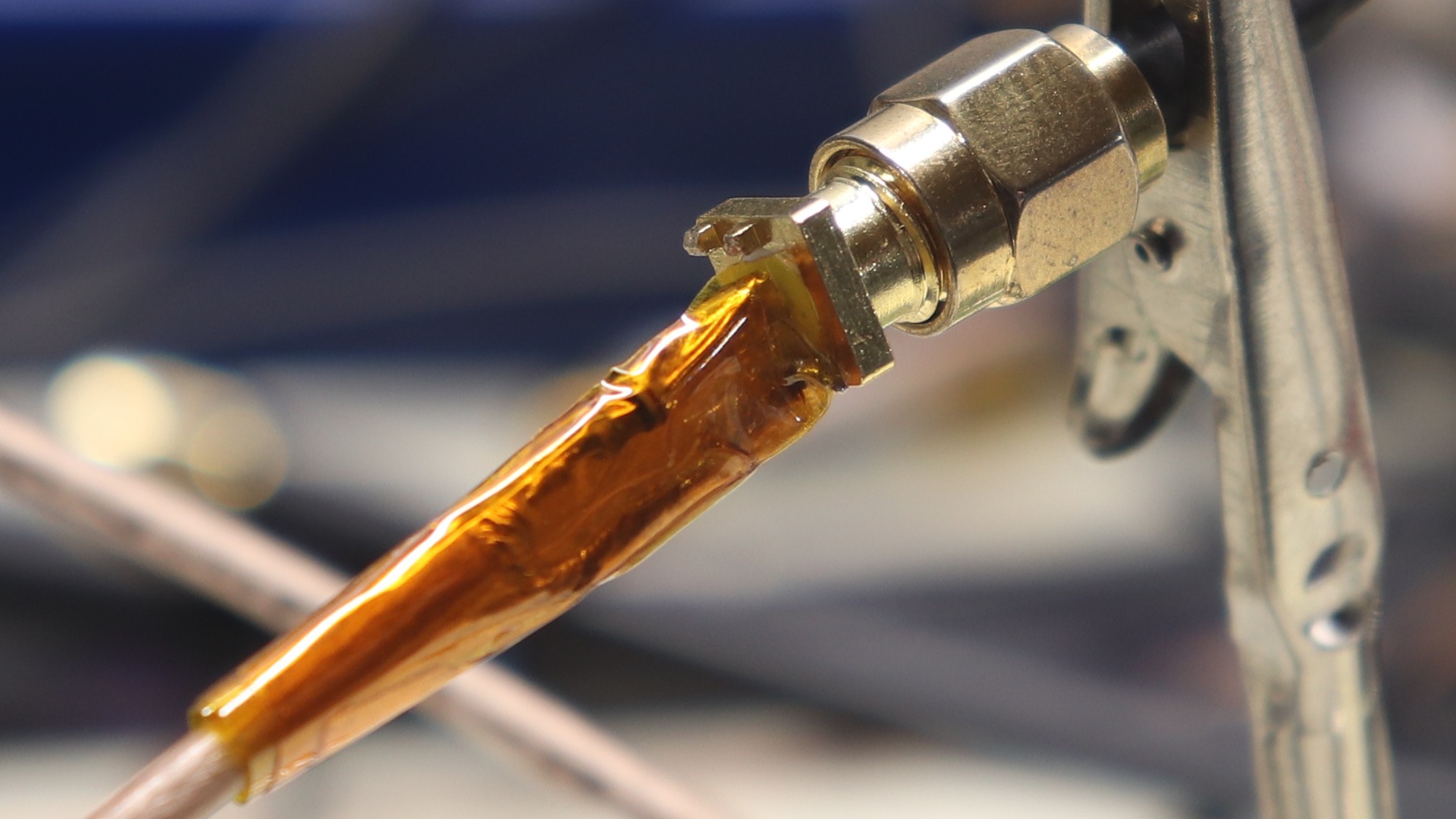
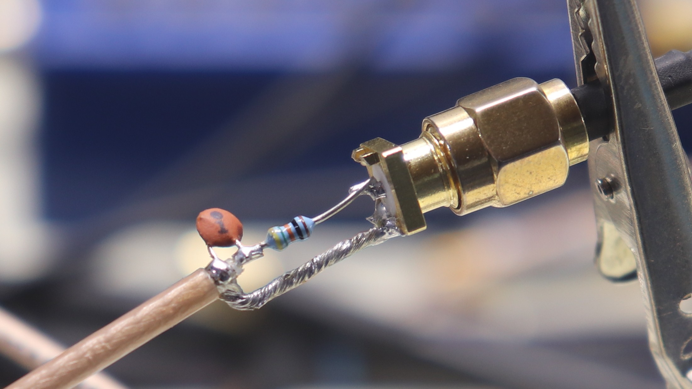
This particular version uses a Stackpole RNF18FTD453R 453-Ohm resistor on the end of a length of RG-316 coax. Cutting a pre-made cable in half creates two probes :-) The resistor provides a 10:1 divisor ratio. It loads the circuit with 500 Ohms. I also have 953-Ohm versions for 20:1 probes. The non-coaxial length of the resistor and shield is 13 mm in this case. It's a little long, and it shows in the performance.
I usually just solder these probes on whatever I want to probe, so for this test, I cut the legs off a SMA end-launch connector and soldered the probe on there.
Measuring A Step
The first test was to measure the step produced by the TDR pulse generator on an SD-24 head in a Tek 11801 oscilloscope. The sampling head is spec'd with a 17.5 ps rise time, while the pulse has a rise time guaranteed less than 30 ps. For this test, I generated a pulse on one channel, which is connected to the modified SMA jack, and measured it through the Z0 probe on another channel.
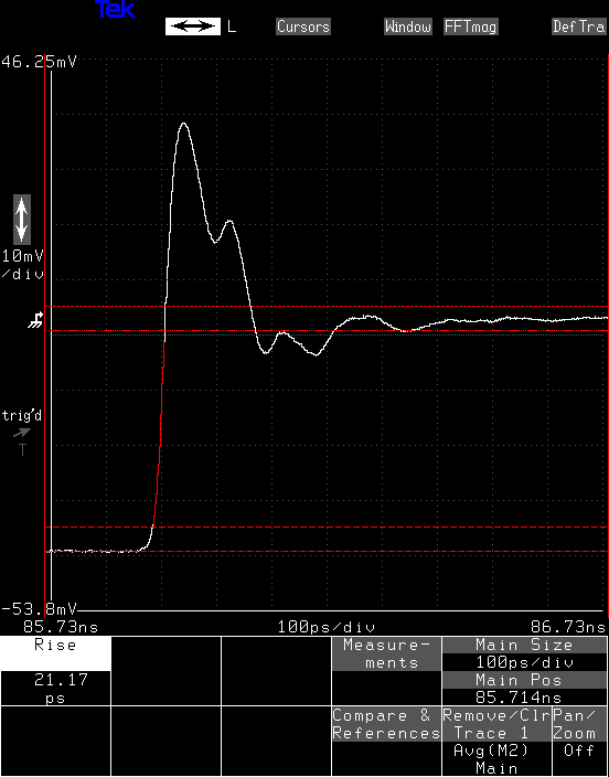
The probe shows a 21 ps rise time, which is at the limits of my equipment, but experiences a really bad overshoot (~100%) that takes around 150 ps to fall back to where it should be. This overshoot is caused by the inductive impedance bump of the resistor and shield run through air.
Look Both Ways
Just to see how much of this was caused by the probe and how much by the SMA connector (a particularly cheap one), I tried the test in reverse, using the SMA jack side as the probe and the resistor/cable side as the probe. I offset the traces horizontally and vertically so you could compare them, since they are basically identical. The most telling evidence was that touching the resistor with a finger caused the same kind of perturbation, indicating that this was indeed the probe and not the SMA connection.
I will repeat this with an SMA M-M coupler at some point to see what that looks like.

TDR Measurement
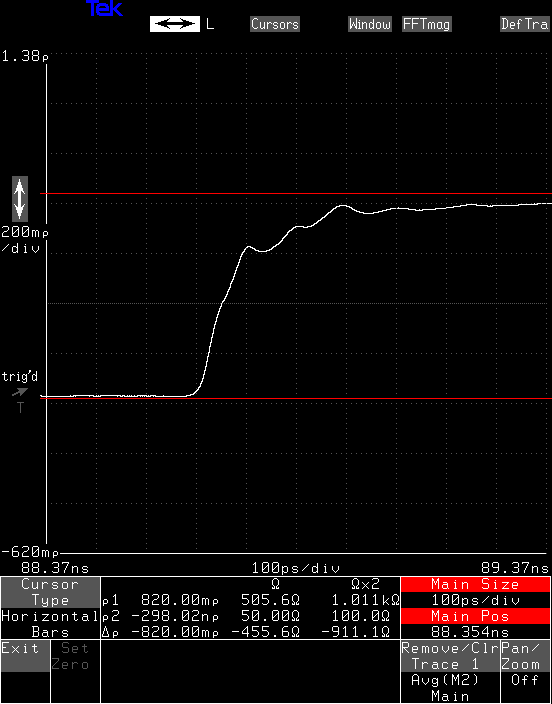
I also tried looking into the probe with the TDR capabilities of the scope. In this case, a pulse is send in reverse down the probe coax, and any reflection(s) are observed. It's important to note that because these are reflections, the timescale is stretched by 2x.
[placeholder for insanely broken editor which deletes style from paragraph tags]
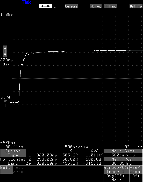
I added both screen shots so you can see that the impedance - note the vertical scale is in Ohms - does eventually rise to 500 Ohms, the level of the top cursor. The bottom cursor is 50 Ohms.
The 13 mm resistor length is about 43 ps electrically, assuming an air dielectric. So, the round-trip reflection of the end of the probe tip should be around 86 ps after the end of the coax. This is roughly at the first little bump in the response, so that kinda makes sense. I'm not sure what to make of this data, really. Can anyone lend a clue?
Shielding
I noticed that adding capacitance with the trusty finger probe knocked down the inductive bump in the response, so I decided to try adding shielding to the probe. First, I wrapped both conductors in couple of layers of kapton tape.
Then added a layer of copper foil:

At this point, it's not really a usable probe anymore, just an experiment. The initial inductive bump is knocked down, now only a 25% overshoot for less than 100 ps or so. This wouldn't be a terrible probe, really, if it were in any way usable physically.

Add Capacitor
So, what about compensating the probe with a lumped capacitor? I held a few caps on the probe to see the effect, and finally decided on a 1 pF ceramic disc. An SMD cap would be a better choice, but this was handy, so I used it.
With this cap in place, the initial rise time is a little longer, but the overshoot is down to around 50%.
I would say that the response is acceptably settled by 400 ps, so the probe is probably OK out to maybe 900 MHz.

122 ps Step
I dragged out one of my pulsers to test this probe with a more realistic waveform - who's really going to use such a contraption with 20-something ps edges, anyway? This pulser, using an ADCMP606 CML comparator, creates a nice 122-ps step. The left image shows the step directly input to the scope; the right image is measured through the resistive probe:


[placeholder for broken editor]
The overshoot here takes around 400 ps to calm down. I would say the probe is not suited for edges this fast.
554 ps Edge
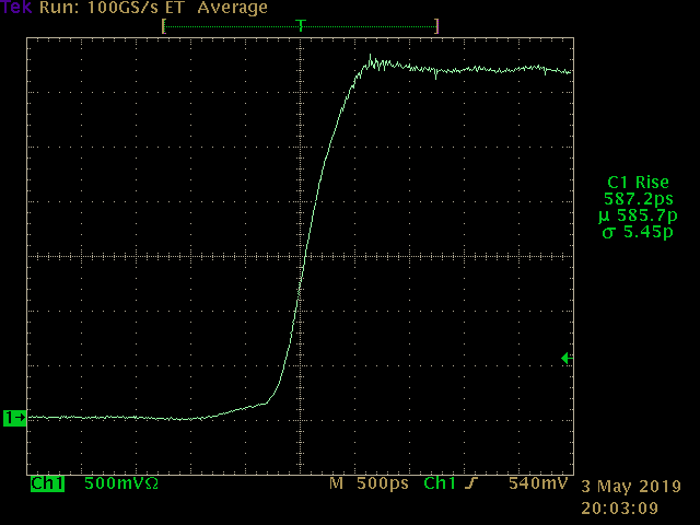
This is an edge from a 74LVC1G04 gate, with a 554 ps rise time (left), and the probe output (right). The rise time measured with the probe is 586 ps. It's also on a 1 GHz scope this time, so both these numbers are a little off; the rise time of the scope itself is in the 300 ps range.

[editor placeholder]
This time, the overshoot isn't noticeable. This is consistent with the observation that the overshoot takes 400 ps to settle.
Conclusion
This probe looks good for edges of around 400 ps or more. That's equivalent to around 875 MHz.
I'm guessing you can push it above 1 GHz just by trimming the leads a bit. You can probably trim at least 5 mm off the leads.
Discussions
Become a Hackaday.io Member
Create an account to leave a comment. Already have an account? Log In.
BTW: https://www.tek.com/datasheet/trimode%28tm%29-probe-family-0
Look at their special resistor with leads. Must be some high frequency ones blessed with holy water?
Are you sure? yes | no
Maybe they use resistive wires to damp reflections. From what I can tell so far, the response problems are edges rattling around in the leads which act as parallel-conductor transmission lines (think of that ancient 300-Ohm twin-lead antenna cable). I might drag out some nichrome and give it a test.
Are you sure? yes | no
You won't be able to solder to nichrome - only crimping or welding.
Are you sure? yes | no
@K.C. Lee you sure can solder nichrome wire. Did that a lot in earlier days. Preparation is needed, sanding, acidic flux and a hot iron is needed.
You're right that in industry nichrome is crimped almost exclusively, tough :) Easier, more reliable when hot and cheaper...
Are you sure? yes | no
@Jan my favorite trick is soldering to aluminum. If you wet a Scotch-Brite pad in mineral oil, then use that to clean the aluminum, it prevents a new oxide layer from forming. Then, you can solder to it with normal tin-lead solder and rosin flux. The auto-ignition temperature of the oil can be as low as 260 C, so it could burst into flames, but I have never seen it.
Are you sure? yes | no
Also, they hire actual wizards at Tektronix. Have you seen the PCBs for their S-4 14.5 GHz sampling head from 1968? It's through-hole except for the sampling diodes themselves on a little hybrid board.
https://www.amplifier.cd/Test_Equipment/Tektronix/Tektronix_7000_series_special/S4.html
Are you sure? yes | no
Not even microstrips? Looks like most of the magic is on the bottom PCB. Not too familiar with RF circuit. That looks like a Diode chopper/switch?
Hmm. Looks like the middle board has plumping - rigid coax. That leaves the top PCB control circuits.
I don't know how these guys test their own equipment when they are at the bleeding edge.
Are you sure? yes | no