 Ted Yapo
In the last log, I looked at a resistive (Z0) oscilloscope - and spectrum analyzer - probe I had been using for a while. That version used a small metal film through-hole resistor. To see how SMD parts would compare, I built and tested another version this morning. This would probably be a single-use probe soldered on a PCB, but the parts are cheap enough.
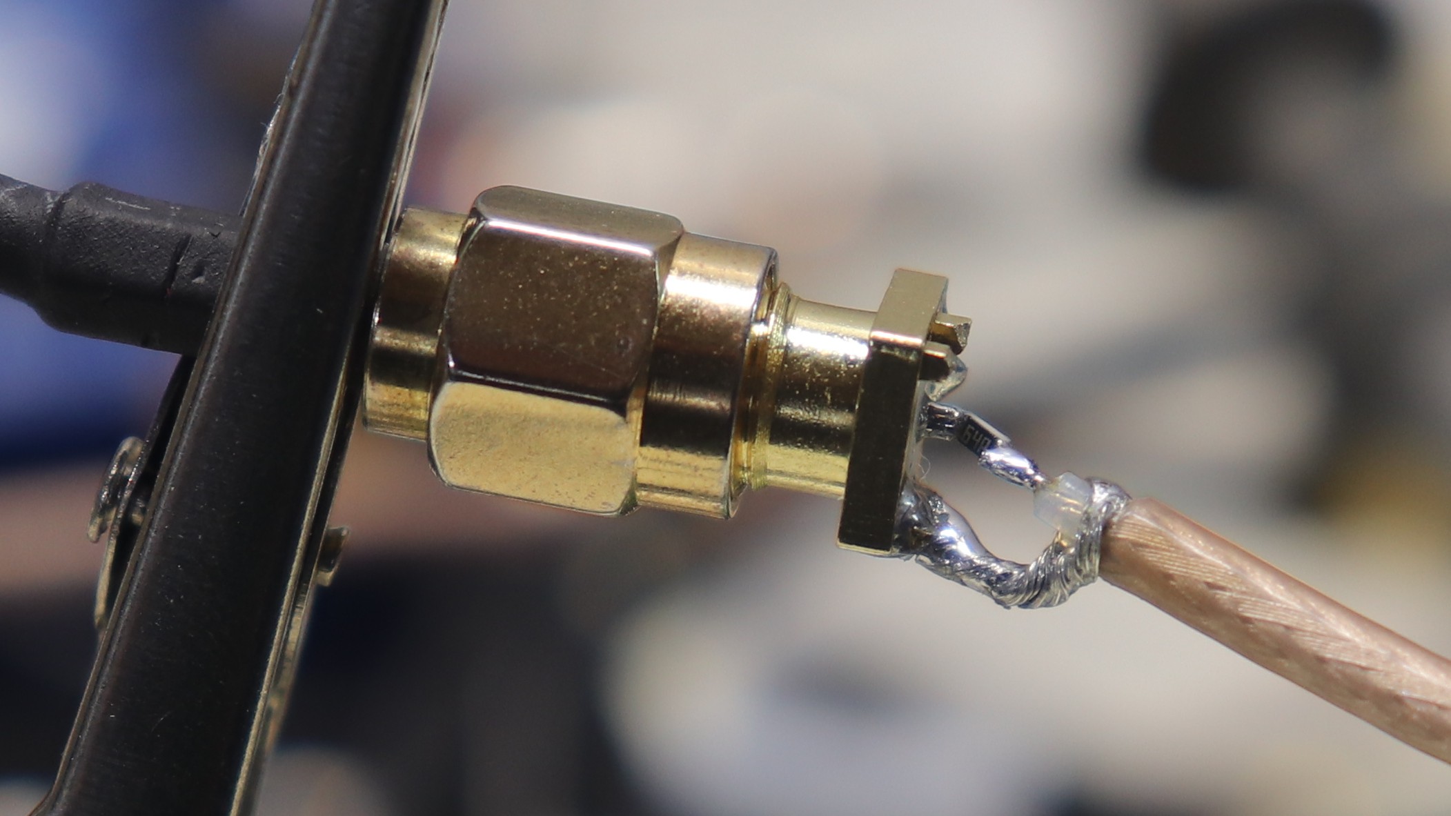
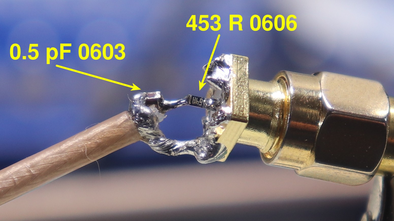
This version uses a 453-Ohm 0603 resistor for a 10:1 probe with an input impedance of around 500 Ohms. Specifically, this uses the cheapest resistor I could find, a Yaego RC0603FR-07453RL. I bought them from DigiKey, but search is broken on their site at the moment, so you get a Mouser link instead.
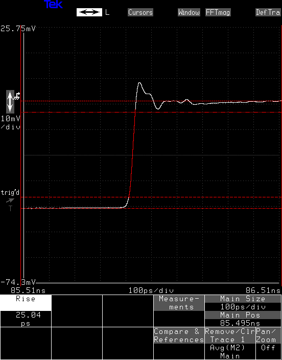
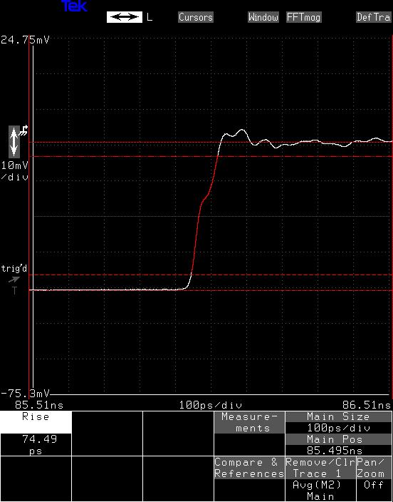
The response looks pretty good right away. The rise time is 25 ps, again, at the edge of what I can measure. There is a 20% overshoot, then a negative ripple that looks fairly well resolved by 100 ps. That indicates it might be a decent probe up to around 3.5 GHz.
Simulation
I took a wild shot at simulating this in LTspice. I looked up some typical package parasitics for 0603 resistors, and modeled the probe as a parallel-wire transmission line. Using 1 mm diameter as the conductor and 4 mm as the spacing, the impedance of such a parallel-wire structure is about 250 Ohms. At a length of 5.5 mm in air, this transmission line should have an electrical length of 18 ps. This is the model I ended up with:
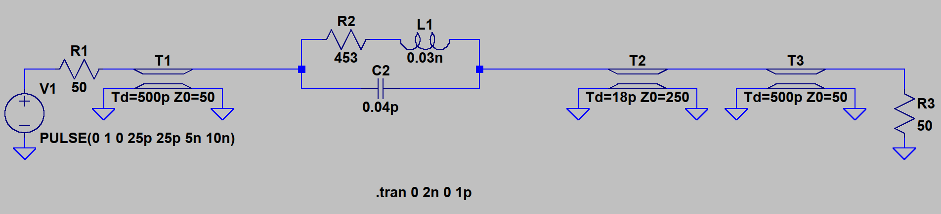
Hit with a 25 ps rise-time pulse, you get this response:
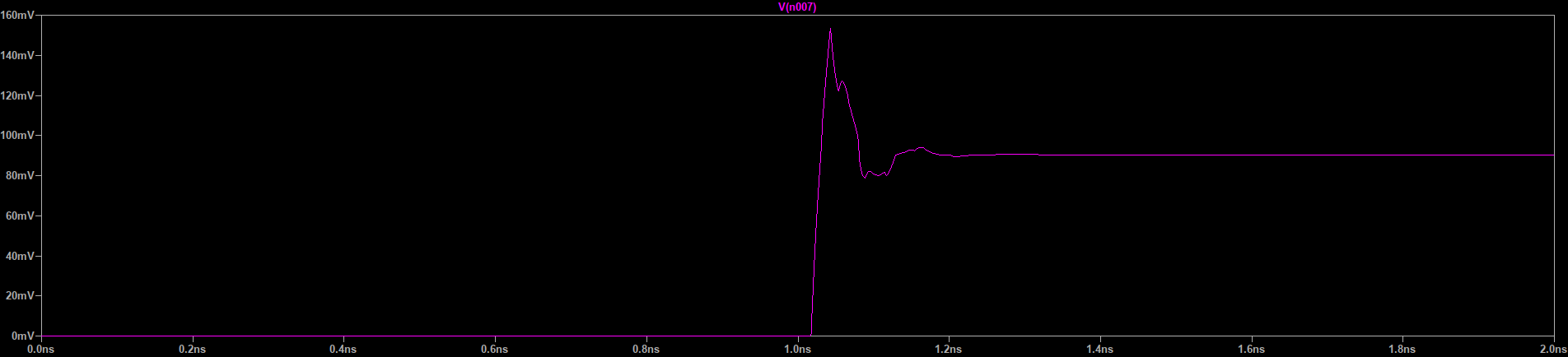
At least qualitatively, I can recognize the basic features of the response. There might be something to this approach.
Compensating Cap?
I found that applying just the right amount of compensating capacitance with my finger could flatten out overshoot and turn this into a 10 GHz probe. Then, I wondered if the same could be done with an SMD capacitor. The smallest one I had in stock was an 0603 0.5 pF, so I soldered it on there to see what would happen. I broke the solderable contacts off of three resistors doing this. SMD components are not meant to take much force.
The result is definitely over-compensated: you can see the capacitive step. This also adds 50 ps to the rise time. Overall, not really an improvement. This is the sort of thing you do with PCB pads, not lumped-element components.
Discussions
Become a Hackaday.io Member
Create an account to leave a comment. Already have an account? Log In.
Found some high frequency resistors: (make sure the description also say high frequency!)
Their MINI-MELF (CMA 0204 HF) series would be a bit more robust but are only up to 300 ohms.
https://www.vishay.com/resistors-fixed/high-frequency/
Are you sure? yes | no
I've seen some like this around, but they can be crazy expensive. For instance, I've looked at "broadband" 0603 capacitors what work into the tens of GHz. They're around $4 each! If there's any way I can get by with the $0.04 variety, I'm going to give it a shot.
At this point, putting actual microwave components on my guesswork PCBs would be a waste, anyway :-)
I'll get there. Slowly, I'm sure.
Are you sure? yes | no