 Ted Yapo
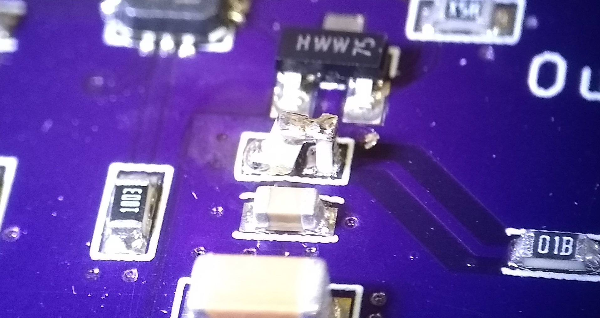
So, after the last test with some through-hole BJTs, I spun a quick PCB to test faster SMD transistors. I had some BFU550A's on hand, which boast an 11 GHz ft compared to the 900-2000 MHz range of the KSP5179's. The output connectors are on the bottom of the board.
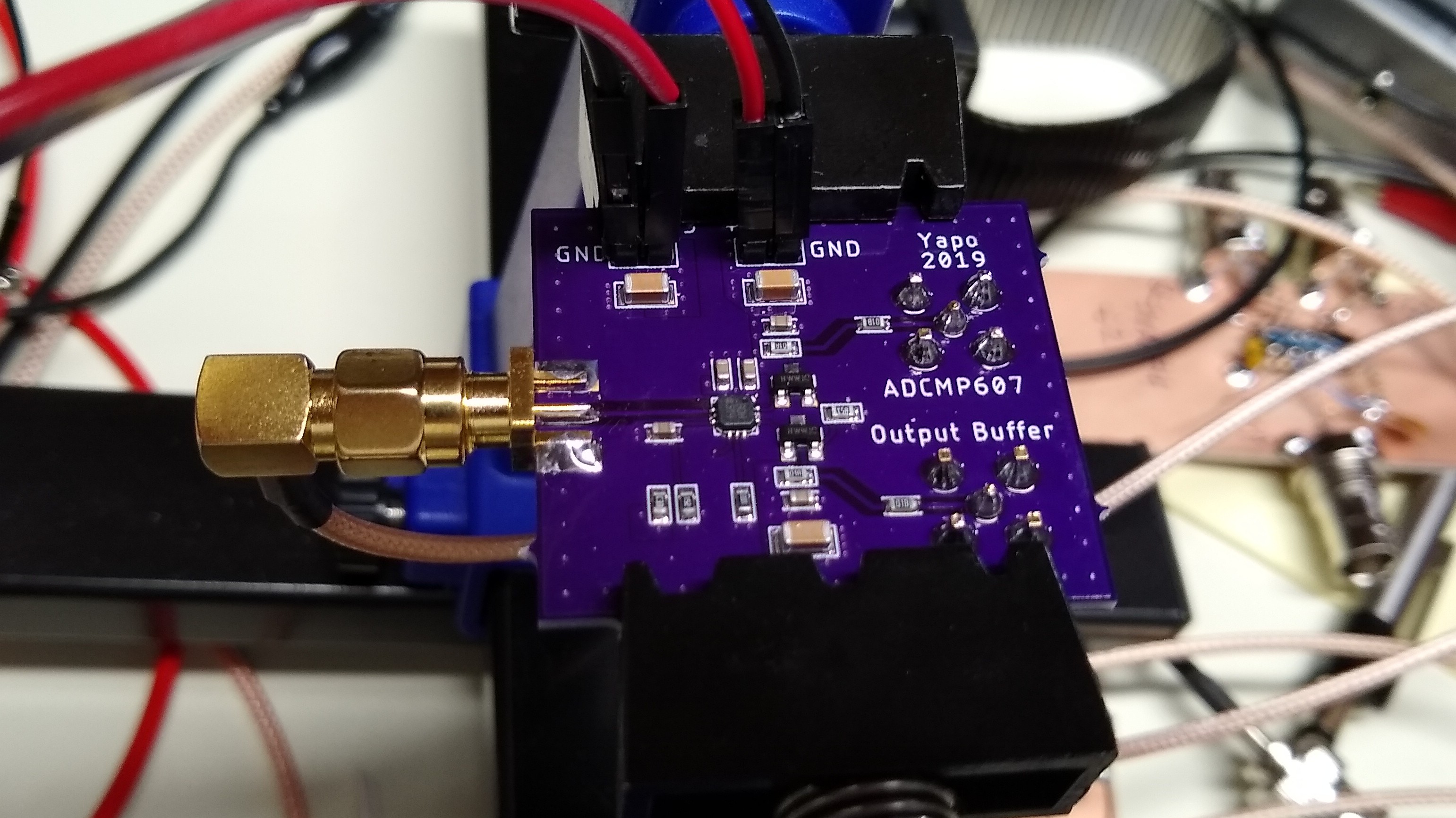
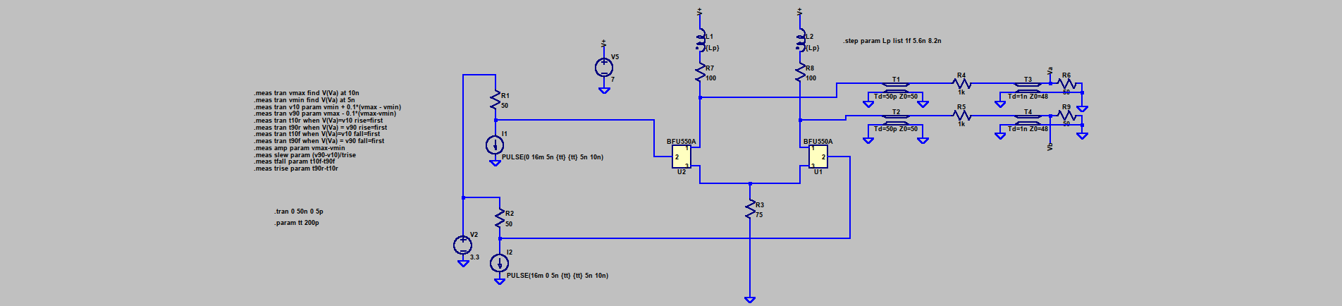
The test circuit uses an ADCMP607 CML-output comparator to generate the differential outputs to drive the pair. The unloaded CML outputs have a 800 mV swing and 50-Ohm impedance. I used 75 Ohms at R3, and 100 Ohms at R1 and R2, as I had before. The ADCMP607 has typical rise and fall times of 160 ps (10% - 90%) according to the datasheet. The output pair has their own supply, which I set to 7 V for the following tests, while the comparator runs on 3.3V.
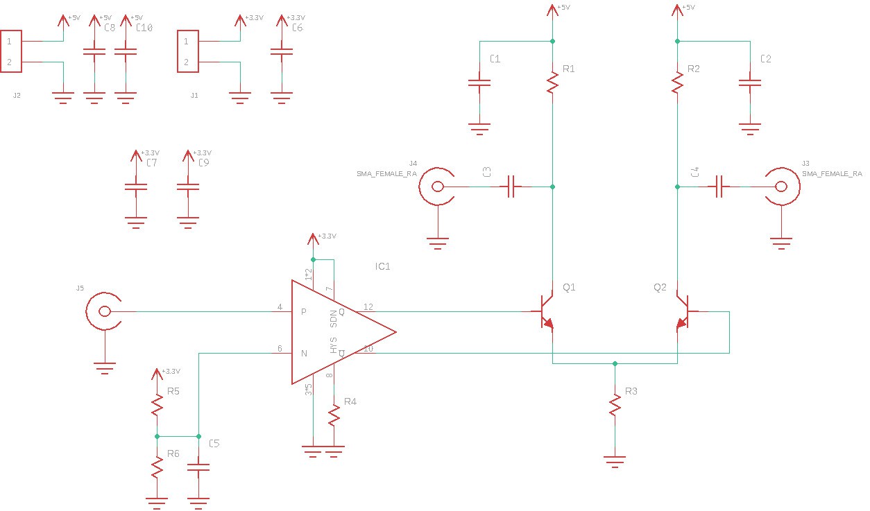
I replaced C3 and C4 in this schematic with 1k resistors to act as 21:1 Z0 probes. This reduces loading effects and also divides the output voltage so that it can be measured on the sampling scope, which has a +/- 2 V input range.
Bench Tests
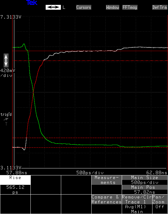
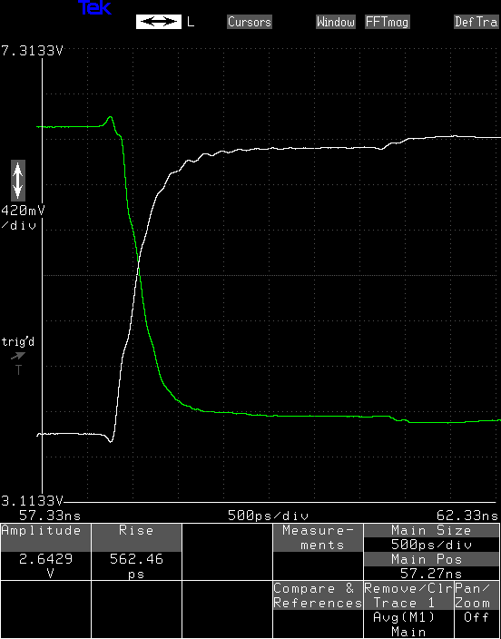
I hooked both outputs to input channels of an SD-24 sampling head in the 11801B scope. The outputs don't look spectacular, but they are certainly faster than the earlier test. In this case, the measured rise time was around 565 ps.
The fall time is around 100 ps shorter, coming in at around 466 ps.
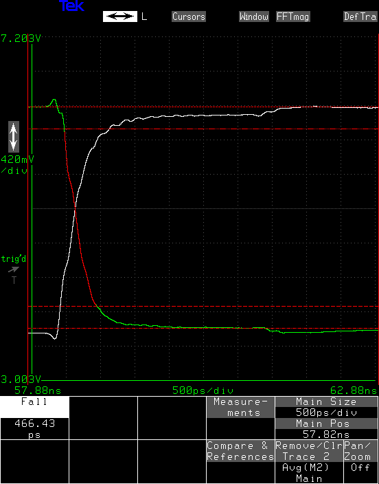
The edges have a definite RC look to them - they start off good, then kind of fall off at the end. There is also an annoying extra step out around 3 ns. This is a reflection caused by my cheap ebay cables - they're around 47 Ohms instead of 50, which results in this kind of nonsense. I was able to simulate this in LTspice, below.
Inductive Peaking
When I threw this quick board together, I forgot about inductive peaking. If the slow transitions are indeed a consequence of an RC structure, adding an inductor in-line with the collector resistors can reduce the rise/fall times. Very roughly, the inductor allows the capacitive component to charge before loading the output with the resistance.
I put together a simulation in LTspice to experiment with inductor values for peaking the outputs. I also added the transmission lines on the PCB and to the scope to model the step effect seen on the bench. A SPICE macro model for the BFU550A is available, which includes the package parasitics, yielding a more accurate result. Unfortunately, the models aren't licensed for redistribution - if you want to use them, you'll have to download them yourself.
I also wrote some code using the LTspice .MEASURE statement to calculate the rise/fall times and slew rate of the outputs.
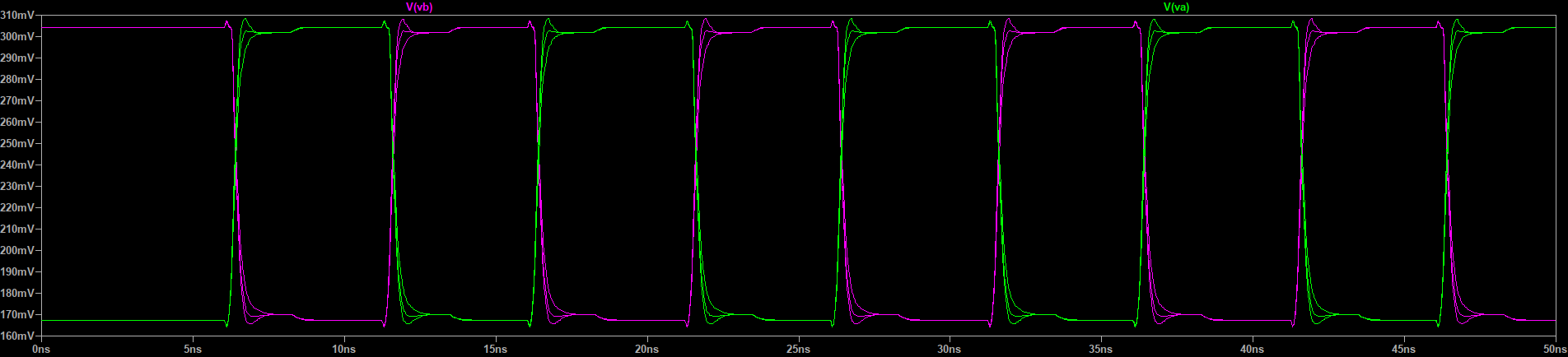
Based on some initial cut-and-try tests, I came up with 5.6 nH as a good value for the peaking inductor. Here you can see runs with no inductor (1 fH), 5.6 nH, and 8.2 nH.
You can also see the later step caused by a simulated 47-Ohm output cable. Setting the impedance of this transmission line to 50-Ohms eliminates the step.
Zoomed in, you can see that without an inductor, the rise definitely droops a bit, with the 5.6 nH, the output looks better, and by 8.2 nH, the output overshoots.
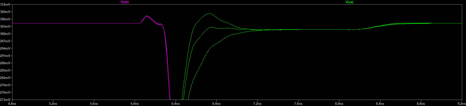
The measured rise and fall times also show the effect. The initial rise time of 434 ps is reduced to just under 300 ps by the 5.6 nH, with only around 25 ps more improvement going to 8.2 nH at the cost of more overshoot. On the other hand, overshoot is not likely to be problem for strobe pulses intended for diode sampling bridges -- it might even prove beneficial.
Measurement: trise
  step    t90r-t10r
     1    4.3427e-010
     2    2.99055e-010
     3    2.73687e-010
These simulation doesn't exactly match the bench tests in the no-inductor case. While simulations show a 434 ps rise time, I measured 565 ps on the scope. I'd like to see these numbers closer, but with all the non-modeled parasitics on the PCB, I'm not going to worry about it too much at this point. It might be something to revisit later.
T-Coils?
T-coils could theoretically produce better results than a simple inductor, but their math is complicated, and they're not off-the-shelf components. In this case, it would probably be necessary to implement the coils as structures on the PCB, which doesn't lend itself to easy experimentation. But, this is a trick to keep in a back pocket in case it's needed later.
Back to the Bench
So, I re-worked the PCB to add an inductor in-line with each resistor. Tombstoning finally comes in handy!
Without the inductor, the rise time measures 562 ps this time.
With the 5.6n inductor, the rise time is reduced to 446 ps, and the shape looks better. There is just a hint of overshoot on the falling edge, and none on the rising.
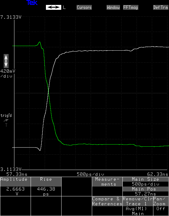
The 8.2n inductor decreases the rise time only by an extra few ps, but noticeably increases the overshoot on the falling edge. There is probably nothing to be gained by adding more inductance at this point.

Conclusions
11 GHz transistors aren't fast enough. The outputs here could just as well have been created with 74LVC gates. I'm looking at some 45 GHz SiGe ones for a next test, but the Vce ratings are all very low, so it may be difficult to get enough voltage swing. In any case, I'm going to make sure to add sites for peaking inductors on the test PCB.
Looking back on the SY88932L laser-driver tests, a peaking inductance probably could improve the rise times. I think I'm going to re-spin the simple test PCB to add inductors and order a few more of those parts for testing.
The sample book of 0603 inductors really came in handy.
Discussions
Become a Hackaday.io Member
Create an account to leave a comment. Already have an account? Log In.