 Ted Yapo
The 11 GHz transistors weren't cutting it, so I had to step up to some silicon-germanium-carbon transistors with a transition frequency of 45 GHz. Luckily, I'm currently experiencing 2019, and such things exist now. These PCB images all look the same, but here is the board:
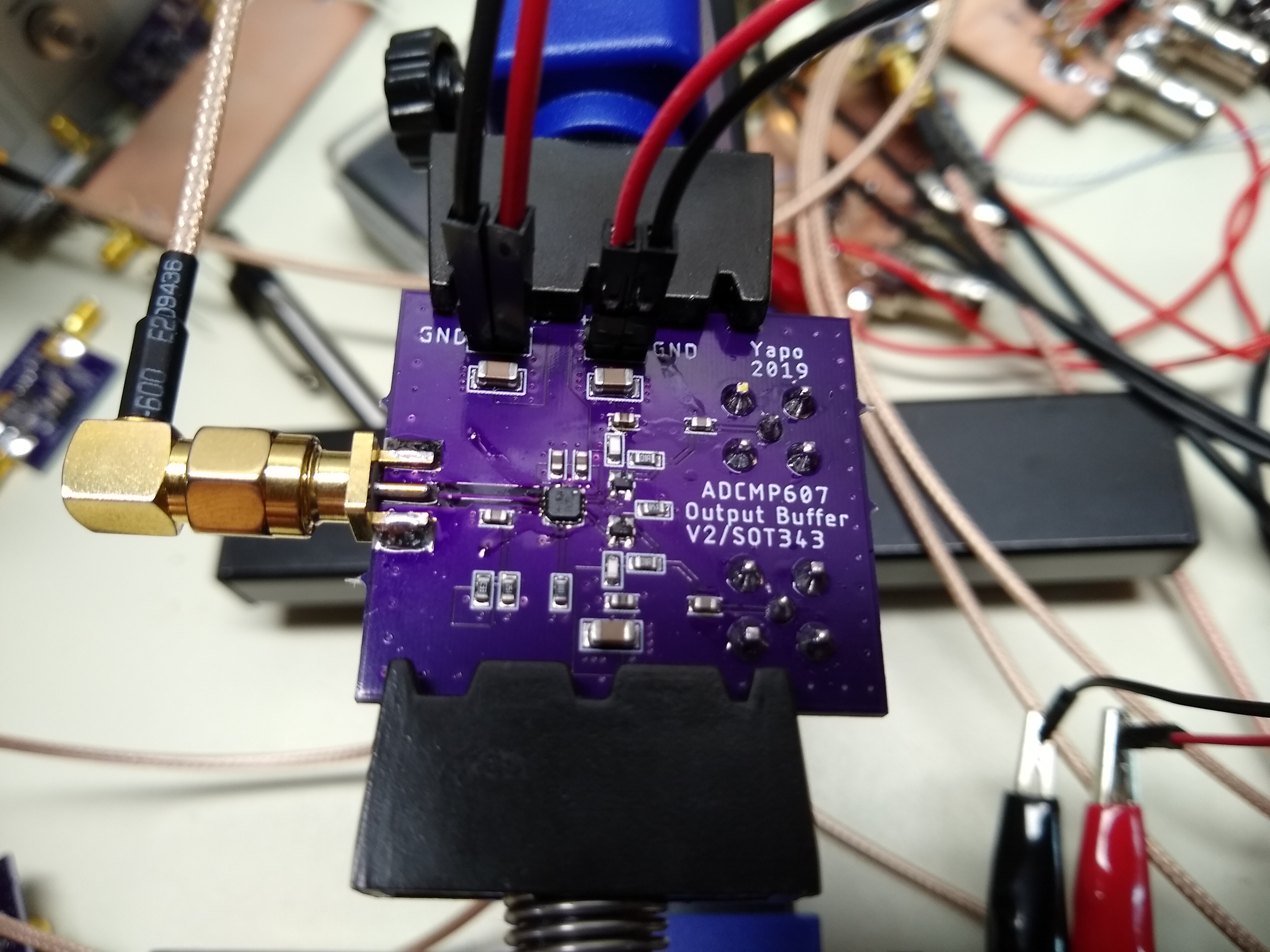
The circuit is very close to the previous one, except with a different footprint for the SOT-343 transistors and added sites for peaking inductors:
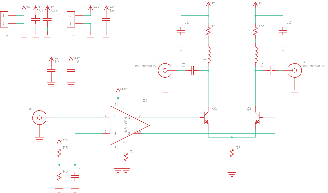
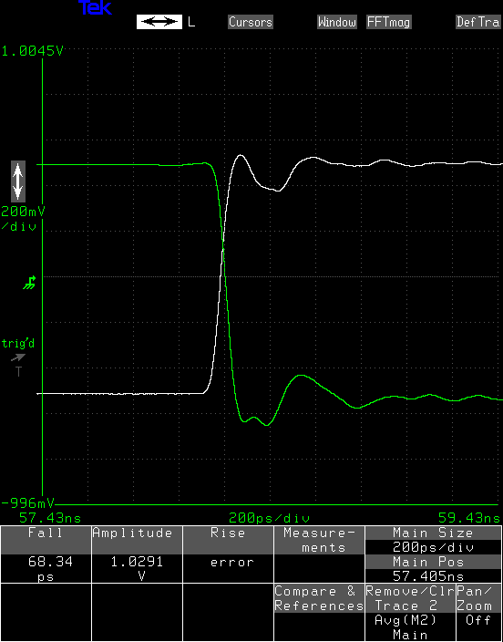
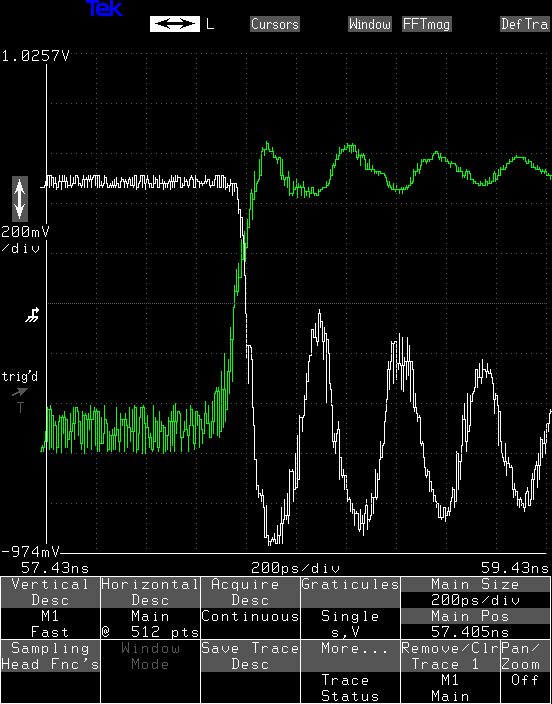
The output transistors are a pair of BFP740ESD's, $0.54 each in single quantities. R1 and R2 are again 100 Ohms, setting the output impedance. R3 is 75 Ohms. They're driven in this case from and ADCMP607 CML-output comparator. The rising output edge from the transistors is under 75 ps, with the falling edge under 70 ps.
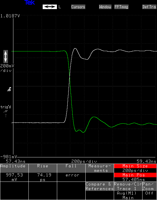
The transitions from the comparator are a relatively slow 120 ps or so (the datasheet says 160 typical), and this may be limiting the output transitions from the transistors. I'm going to spin a PCB for a ADCMP572 comparator with 35 ps transitions to see how much faster the transistors will go. Even as-is, this is fast enough to move forward with the design.
The output impedance of the circuit is 100-Ohms, set by the collector resistors. When loaded by the 50-Ohm scope inputs, the outputs have a 1 V amplitude. This means they're 3V unloaded, which is exactly the design point: perfect.
With the PCB layout, there is enough stray inductance that I just replaced the lumped inductors with 0-Ohm resistors; anything more caused undesirable ringing.
The lousy look of the step is due to some reflections on the PCB. I rushed this one out, and made some layout mistakes. Maybe I'll take a little more time on the next one.
The transistors have a maximum Vce of 4.2 V, set by internal ESD protection devices. I was able to run the output stage at a supply voltage of around 5 V, by which time it had achieved maximum amplitude. At around 5.5 V, the output started to tear:
this example also had 6.8n peaking inductors on the board, which causes the overshoot and ringing. The interesting thing is the high-frequency noise, which could be avalanche breakdown of the ESD protection devices, high-frequency parasitic oscillations, or an artifact of the sampling oscilloscope interacting with the waveform. I think the lesson is to keep the supply voltage to 5 V or less, but this is enough to give the 3 V output swing.
The bottom line is that this $1 pair of transistors do a better job than the $10 laser diode drivers I had been using. It's amazing to me that you can get these kind of speeds with discrete transistors, but you can.
Discussions
Become a Hackaday.io Member
Create an account to leave a comment. Already have an account? Log In.