 Ted Yapo
So, I combined a few ideas from previous logs and prototyped a differential pulse generator with 74AC CMOS gates. The goal is to have a differential output with large swings for short pulses. I got it to 10V swings and around 1.6 ns pulses.
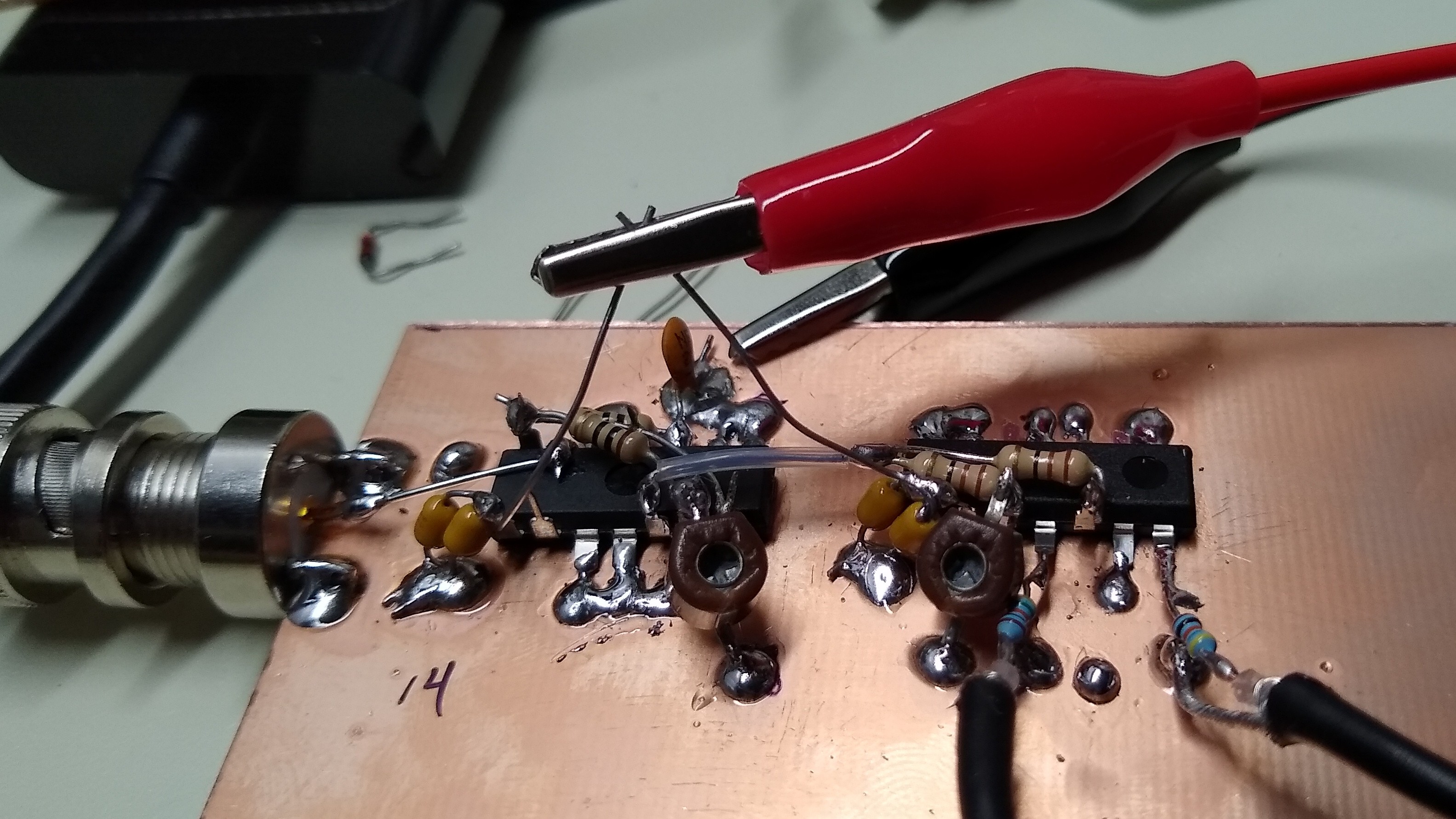
There are two parts to the circuit: an edge-to-glitch converter and the XOR differential stage from previous logs. Both have capacitive trimmers for fine adjustment. I got smart and grounded the correct side of the trimmers this time, so they can be adjusted with a metal screwdriver without affecting the circuit.

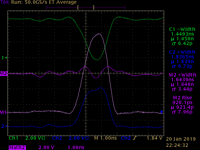
With some careful tuning of both trimmers, I ended up with the output shown below. Ch1 (green) is the output of the upper XOR, it swings from 5V down to 0 for the pulse. Ch2 (blue) is the lower XOR output; it swings from 0 up to 5V. The magenta/pink traces are math combinations of the two. The magenta trace is the sum of the two outputs - ideally, it should be a constant 2.5 V; any wiggles are errors in the two outputs. The pink trace is the difference between the two outputs - the differential signal. It's not a bad pulse, really. It is 1.6 ns wide, and has an amplitude of about 10V. With the 24 mA output capability of the 74AC gates, it should have no problem driving a diode sampling gate through relatively large resistors (perhaps a few hundred ohms).
Note how a lot of the ringing on the upper and lower pulses have cancelled in the differential pulse. That's a neat side effect that I hadn't anticipated.
This is probably OK for a first test, although I'd really like to be able to do this at least 3x faster. 74LVC1G gates might come close.
Discussions
Become a Hackaday.io Member
Create an account to leave a comment. Already have an account? Log In.