 Ted Yapo
This is the first in a few logs to document everything that went into getting the first sampling head to work. I needed a new edge generator with a build-in delay to line up the pulse edge with my sweep delay generator (details next log). I ended up making this with a 74AC14 and 74AC04.

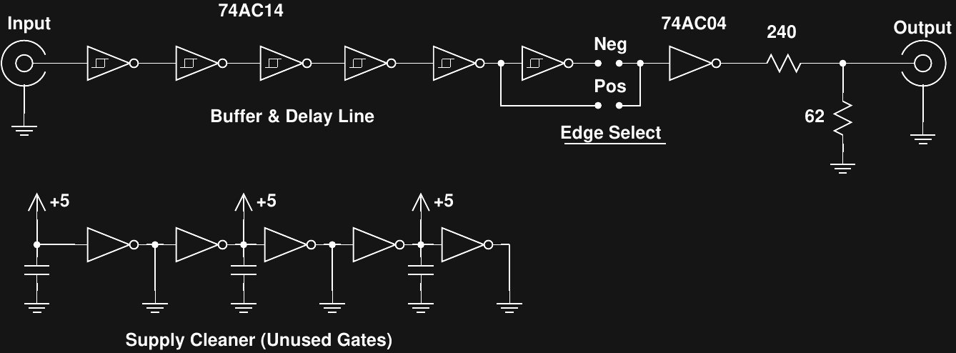
The 74AC14 chain delays the input pulse, and you can select the polarity by choosing the output tap. One section of a 74AC04 is the output buffer/driver, and there's a resistive divider to provide a source-terminated 500 mV output into a 50-ohm load (100 mV unloaded). With the unused portions of the 74AC04 I made a "supply cleaner." This just connects unused *outputs* of the gates to Vcc and GND to essentially add more supply pins to the package. The MOSFETs in the output structures of those gates have a decently low impedance and hopefully help with the notorious supply problems of the 74AC family.
I measured the output of this new circuit with a few scopes, including the new sampling head.
1 GHz Tektronix TDS-784D
(It's a modified TDS-754D, but don't tell anyone :-)
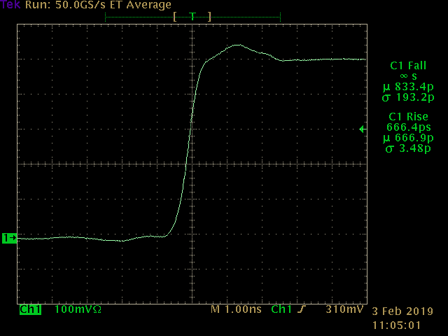
Here's the rising edge of the pulser on a 1 GHz scope. It looks pretty good except for a little bump about 1 ns after the edge. This isn't a reflection: there's not enough space anywhere to produce this timing. I think it's the 74AC04 itself. In any case, it's a feature on a short timescale that we can use to check other scopes. The rise time of the edge is 667 ps, not counting the contribution of the scope itself (it's likely under 600).
1N5711 Sampling Head
(It's a homebrew sampling head, tell anyone you like :-)
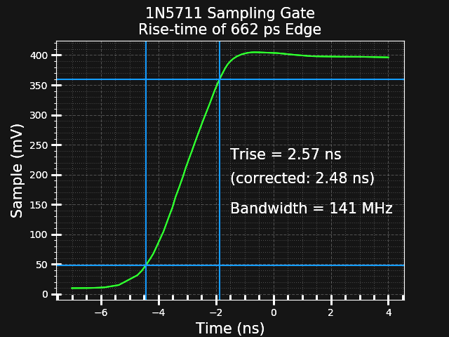
I painstakingly collected data for this edge using the same setup as before. It ended up being 97 points total, averaged over millions of input pulses. The calculated rise time for the sampling gate is 2.48 ns, for a bandwidth of 141 MHz. This is close to the 155 MHz I previously estimated with the fall time of a different pulse.
Interestingly, the little bump at the top of the pulse is just barely visible. I think this "scope" just doesn't have quite enough bandwidth to show the bump.
I'll come back to this image in a later log. There's a lot going on to capture this data.
300 MHz DS3202A
(It's a modified DS2072A, but don't tell anyone :-)
This 300 MHz scope has just enough bandwidth to start to render the bump at the top of the pulse.

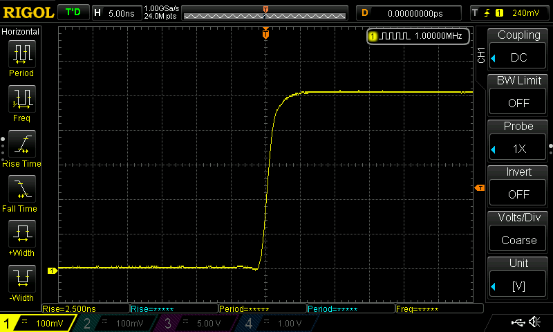
100 MHz DS1104Z
(It's a modified DS1054Z, but don't tell anyone :-)
On a 100 MHz scope, there's no bump on the pulse at all.
Conclusions
It certainly seems to behave like a 140 MHz scope - the captured waveform looks better than the 100 MHz commercial scope and worse than the 300 MHz model. So far, so good.
Discussions
Become a Hackaday.io Member
Create an account to leave a comment. Already have an account? Log In.