 Ted Yapo
This is what I've been using so far, and will be until the new PCBs come back. It's a little primitive, and not entirely stable, but it allows adjustable delays with a resolution of tens of picoseconds. It's also really interesting to see how ground bounce and supply sag influence the high and low voltages of the "other" channel with these two output drivers in the same package.
The circuit has a pulse input and two outputs. You can tune the timing of one output relative to the other with a control voltage. The whole thing is breadboarded ugly/dead bug style on some copper clad. There's plenty of room for other stuff :-)

The circuit isn't very complicated. An NTE-618 varactor diode is used in an RC delay circuit to move the edge of one output relative to the other. The stationary edge uses a similar RC circuit with a fixed capacitor to place it approximately in the middle of the range of the variable output. You can tune the output over about 10 ns, and a 20-turn potentiometer allows setting the delay with a resolution below 50 ps.
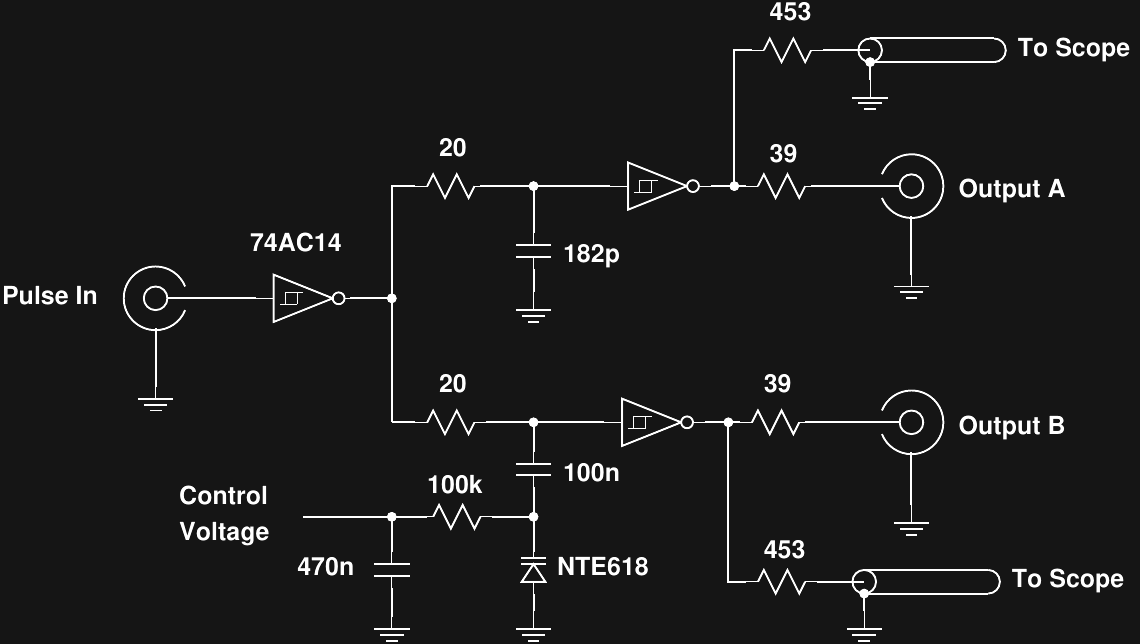
The control voltage is non-linear and uncalibrated, so I tapped the outputs and monitor them on a 300 MHz scope to determine the relative time between the edges. The modern Rigol scope has better statistics on this kind of measurement than my ancient 1 GHz Tektronix, so I used it. Due to the large levels of jitter in the system, you have to average 20-50 measurements to get a stable result. This isn't as limiting as you might think, since you can use MHz repetition rates.
Calibration
I had intended to retire this circuit and wait for the fancy new PCB to arrive, but after a brilliant observation by @salec on the last log, I think I'll do a few more experiments with it. The awesome idea was to calibrate delay generators by connecting them as feedback oscillators and measuring the resulting frequency. This frequency is related to the inverse of the delay time and frequencies are easily measured to parts-per-million accuracy.
I think I'll wire up a 12-bit DAC and op amp on the PCB to allow driving the varactor with 0-12V, hook up some kind of oscillator circuit, then try to calibrate the delay vs voltage. It's too bad my bench frequency counter doesn't have a PC connection. I might be able to use the spectrum analyzer, although it would take a bit of coding. Actually, it might be easiest just to find one of the OCXOs, TCXOs, or rubidium oscillators I have tucked away and throw together a quick frequency counter on an FPGA.
Discussions
Become a Hackaday.io Member
Create an account to leave a comment. Already have an account? Log In.