 Ted Yapo
I was reading about coax delay lines today and was reminded about this kind of compact coiled delay line. It's essentially a coiled transmission line created by winding fine wire around a conductive tube. So, I made one - completely randomly - from stuff I had around just to see what it would do.
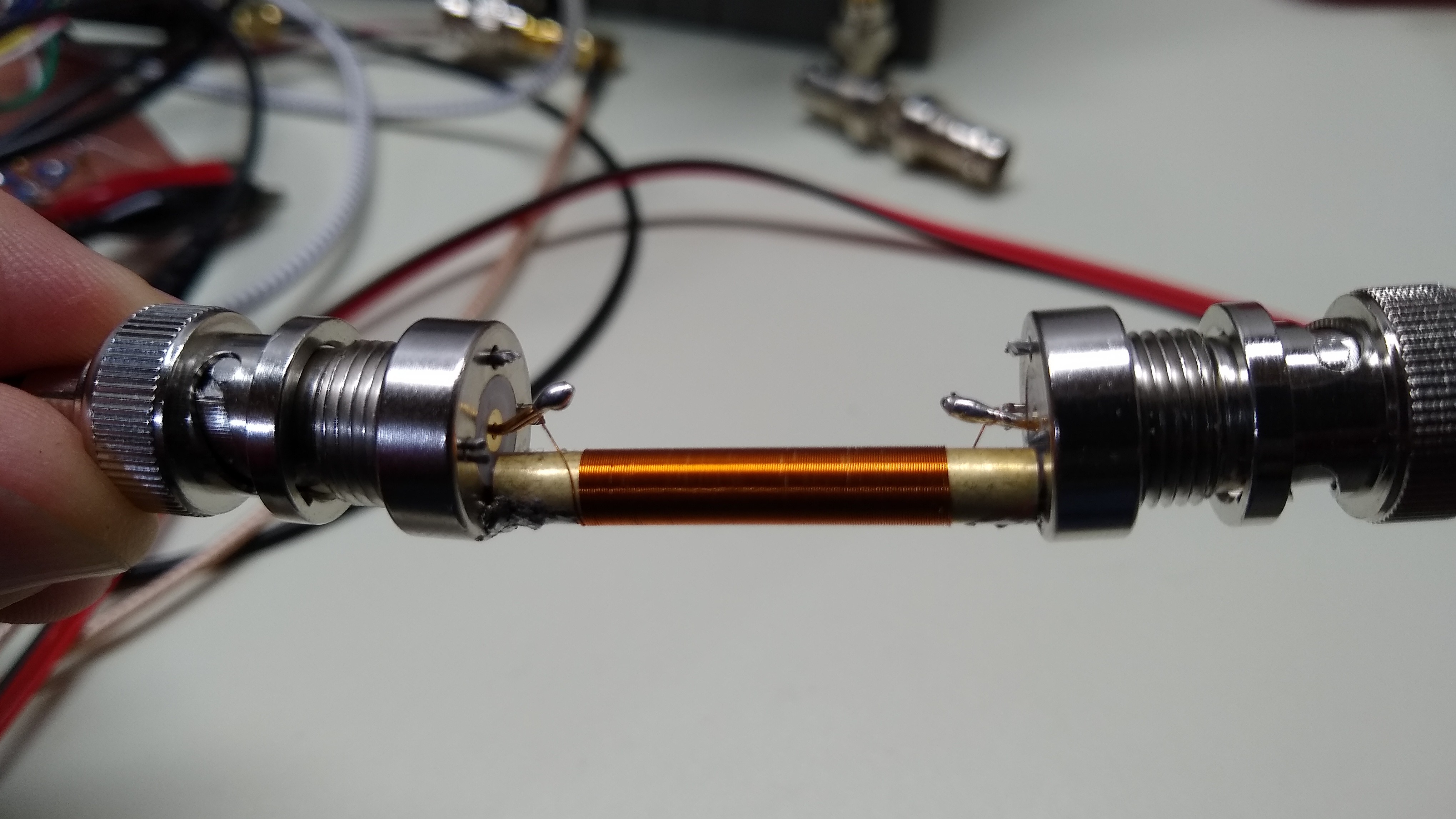
To make the assembly, I soldered a length of 4.8 mm diameter brass tubing between the ground lugs of two BNC jacks, then wound a length of #36 wire on the tubing. I don't know the exact length of wire or number of turns, but the coil itself is 24 mm long. Some calculations show that this should be approximately 2.93 m of wire.
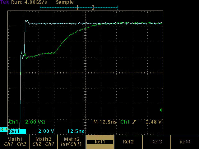
The first test of the delay line was to hook it up to an oscilloscope to measure the delay and bandwidth. The delay line feeds channel 2, while a reference pulse, identical to that going into the delay line, is shown on channel 1.

The delay on both the rising and felling edges is very close to 20 ns. This corresponds to a speed of 1.465 x 10^8 m/s, or 0.488 c in the wire. In the coiled structure, this is equal to 1.2 x 10^6 m/s or 0.004 c. That's pretty slow!
This delay is equivalent to 4.03 m of typical coax with a velocity factor of 0.66.
The bandwidth of the delay line can be estimated from the rise time of the pulses. Corrected for the rise time of the input pulse (9.25 ns), the output pulse has a rise time of 29.3 ns. This is equivalent to a 3 dB bandwidth of 11.9 MHz. Wow, that's not very good.
I'm guessing that the bandwidth is degraded by capacitance between adjacent turns in the coil. Maybe it could be increased by adding a little space between them.
When I get a chance, I'm going to measure the characteristic impedance of the line. Not quite sure the best way to do that yet. TDR or VNA?
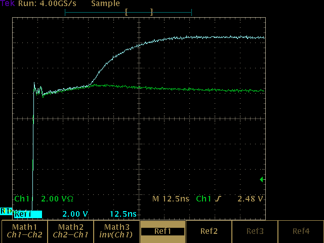
TDR Tests
I fired up the #Tiny TDR this morning to test the characteristic impedance of the line. Here is a shot of the step from a 33 cm length of cable into the delay line. The Cyan trace (top) is the reference trace with just the cable connected to the TDR, and the green trace (bottom) is with the delay line connected. There is very little, if any, step at the boundary, indicating that the delay line has a characteristic impedance close to 50 Ohms.

Here it is on a longer time-scale where you can see the end of the delay line. From a TDR perspective, the end looks like it's terminated with a capacitor, although this also mirrors the rise-time measurements taken with the scope. There's some deep connection here that's evading me at the moment. Again, the cyan reference trace is the output cable alone; the green is with the delay line attached. At this scale, you can see some slope to the trace before the end of the delay line.
Finally, here it is without a 50-ohm terminator at the end of the delay line (cyan), and terminated (green). Again, it looks like little reflection from the terminator. You can still see some small rise and fall of the terminated trace, though. Maybe the impedance is a little higher than 50 ohms?
Discussions
Become a Hackaday.io Member
Create an account to leave a comment. Already have an account? Log In.
did you also cover the wires with alu/copper foil for extra shielding and capacitance ?
Are you sure? yes | no
no, I didn't, but that would be a great trick to reduce the impedance of the line if needed. Some quick tests indicated it was fairly close to 50 ohms as-built, and I could get it lower than that by pressing a finger against the coil - the old finger capacitor trick.
I'm measuring it now, and it looks pretty 50-ohmish. Will post results ;-)
Are you sure? yes | no
now that I measure it more closely, that may be what it needs - just a little, though
Are you sure? yes | no