 Szabolcs Lőrincz
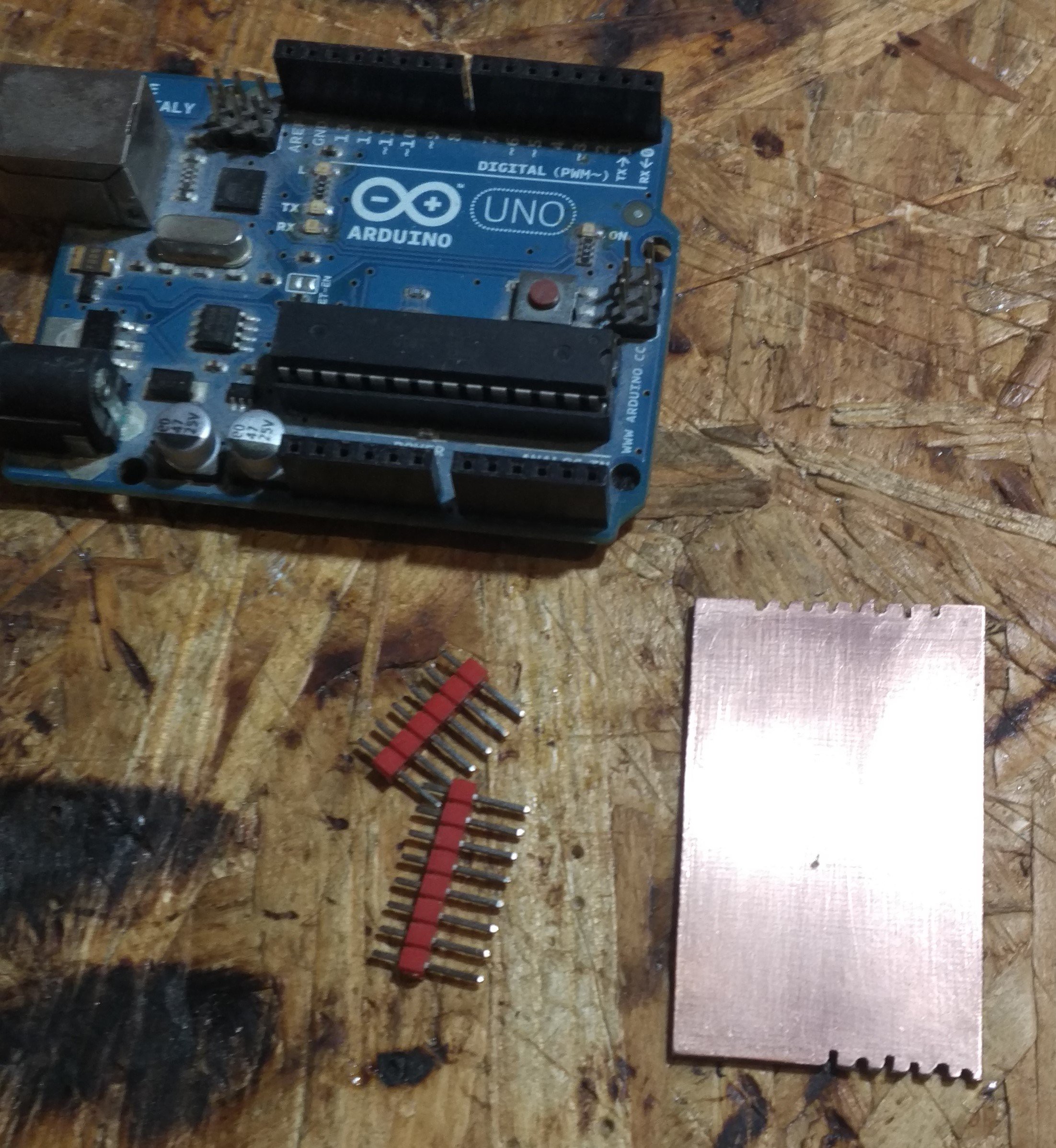
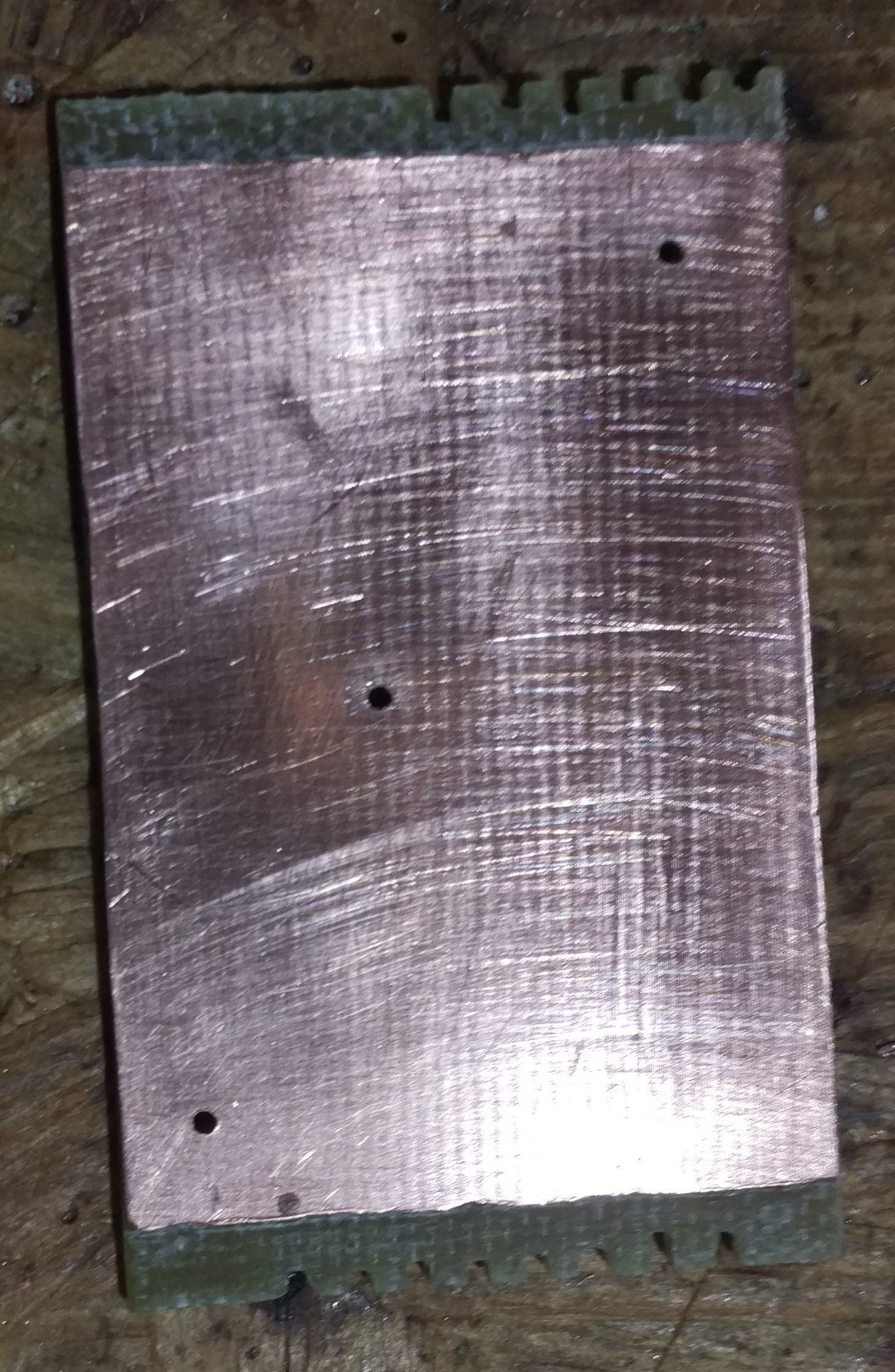
Now that all is working, it is time to assemble the thing into a whole. It will take the form of an Arduino shield. So I took a piece of PCB board, cut it to size, and used it as a foundation for my project. So basically, this is a circuit assembled on a sheet of FR4 with copper conductors, but it's just a part of it, so I hope it would still count as freeform.
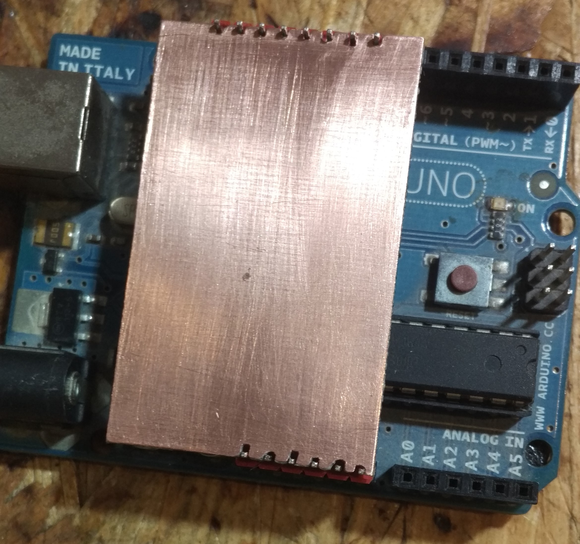
Anyway, here's the pictures from the process. The shield connects to the upper part of the 'duino, since we don't need analog inputs and have enough digital GPIOs. I didn't want to drill holes for the pin headers, so I fitted the board between the headers and filed a little cut for them to fit better.
 |  |
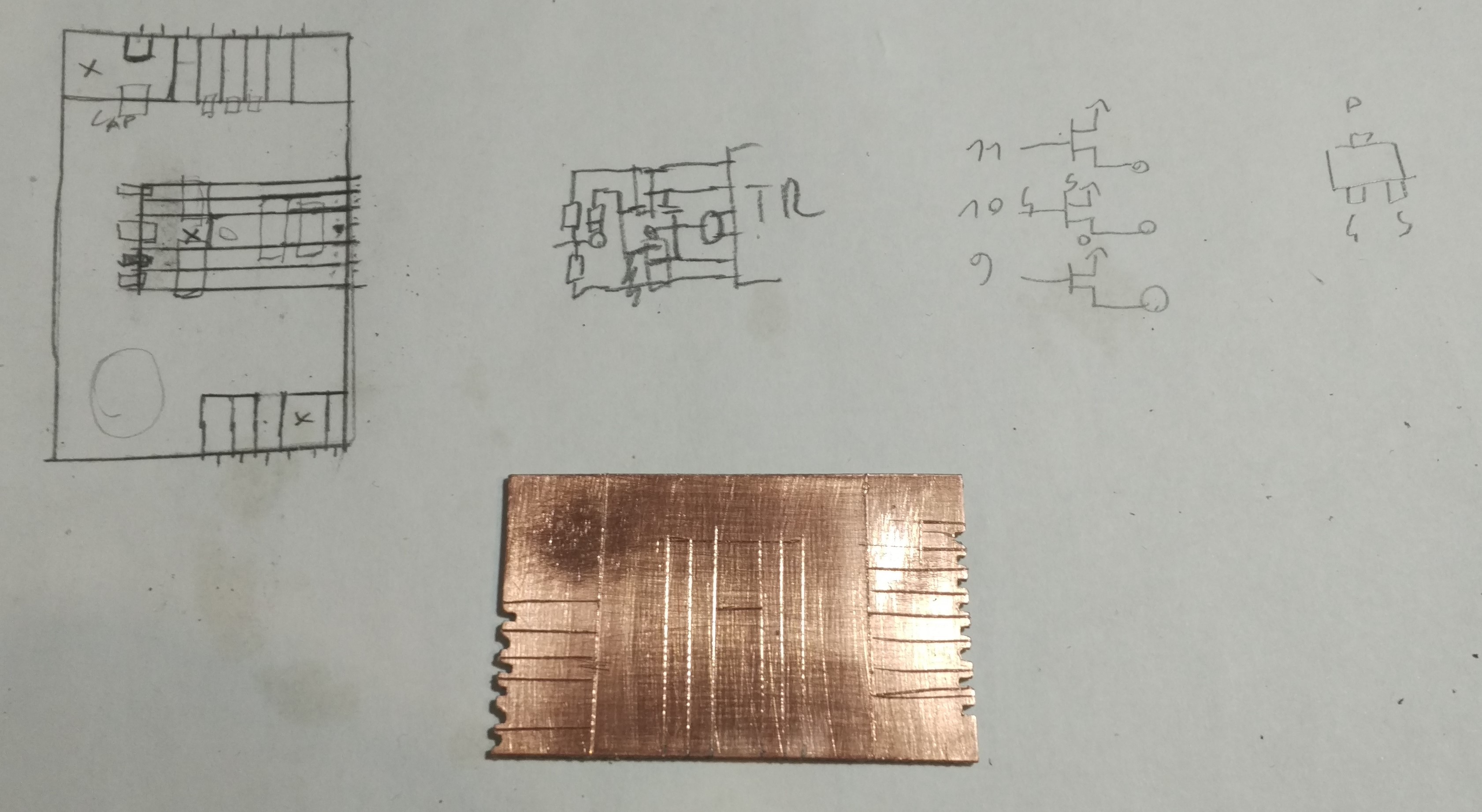
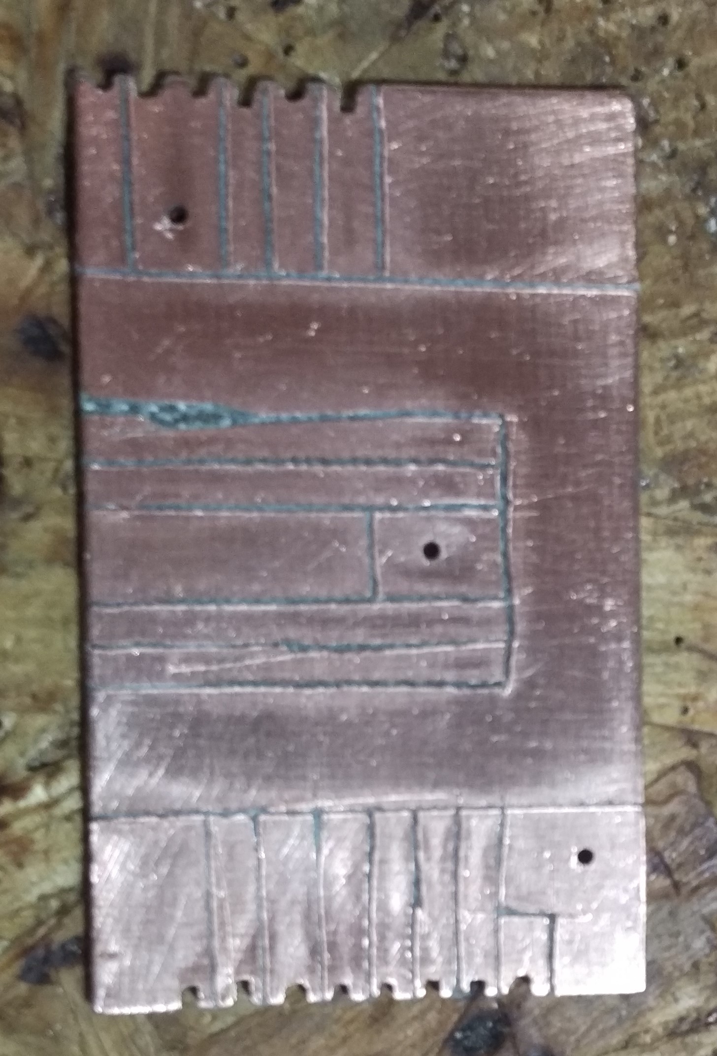
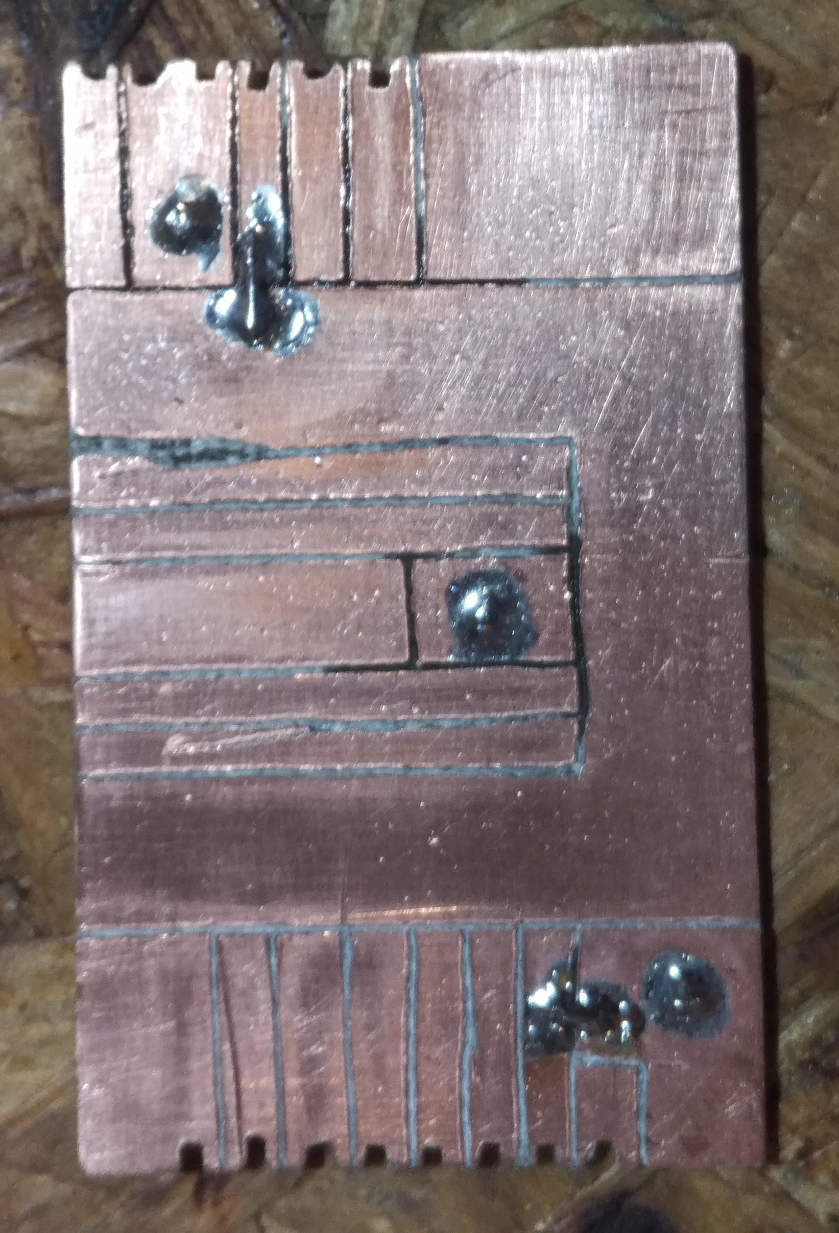
After planning the routes, I cut out the separations with a stationary knife, drilled and soldered some vias and bridges, and the board was ready to populate. It's not the prettiest thing I have to admit, but once the components are on, it'll look a little better.
 |  |  |  |
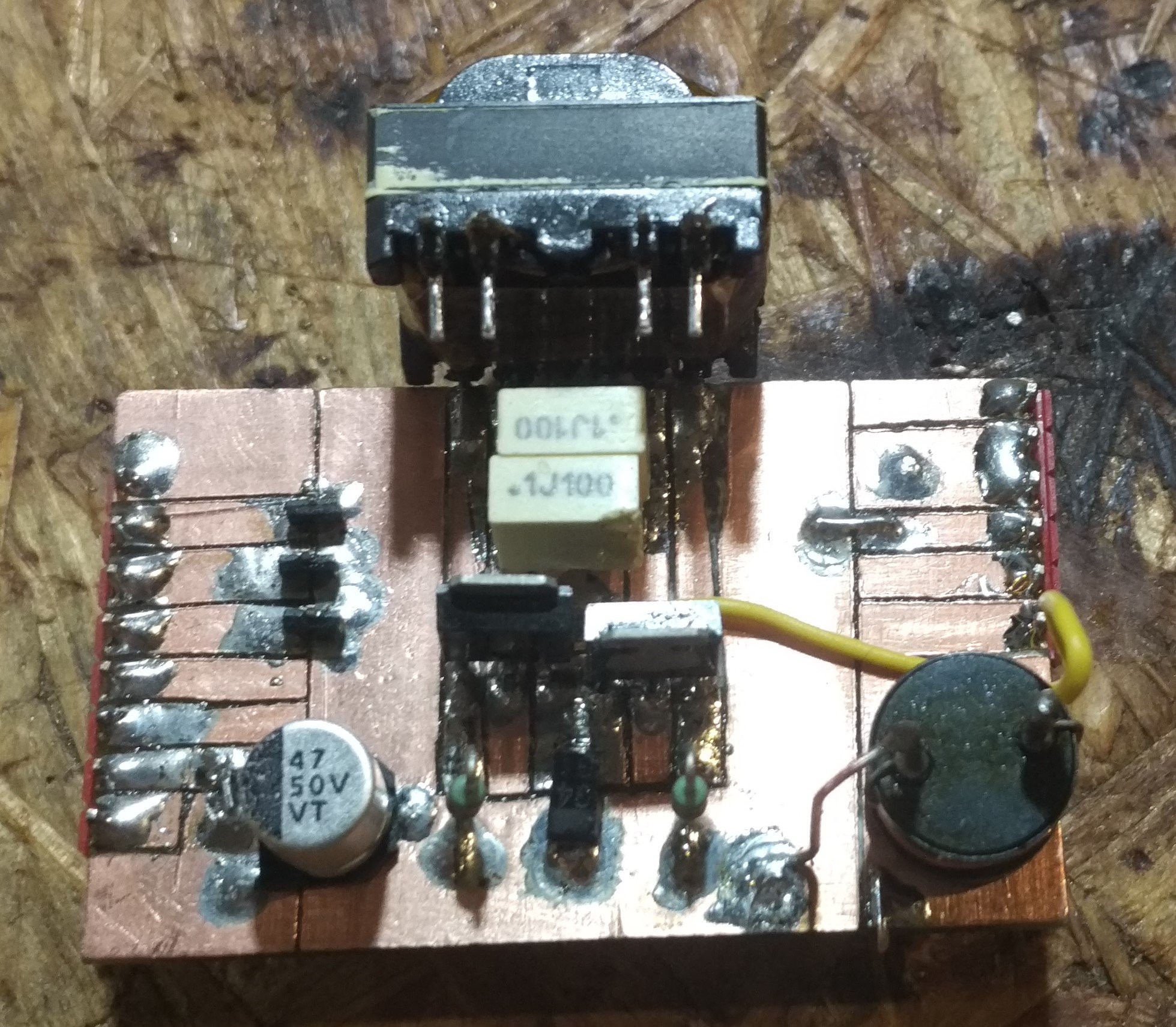
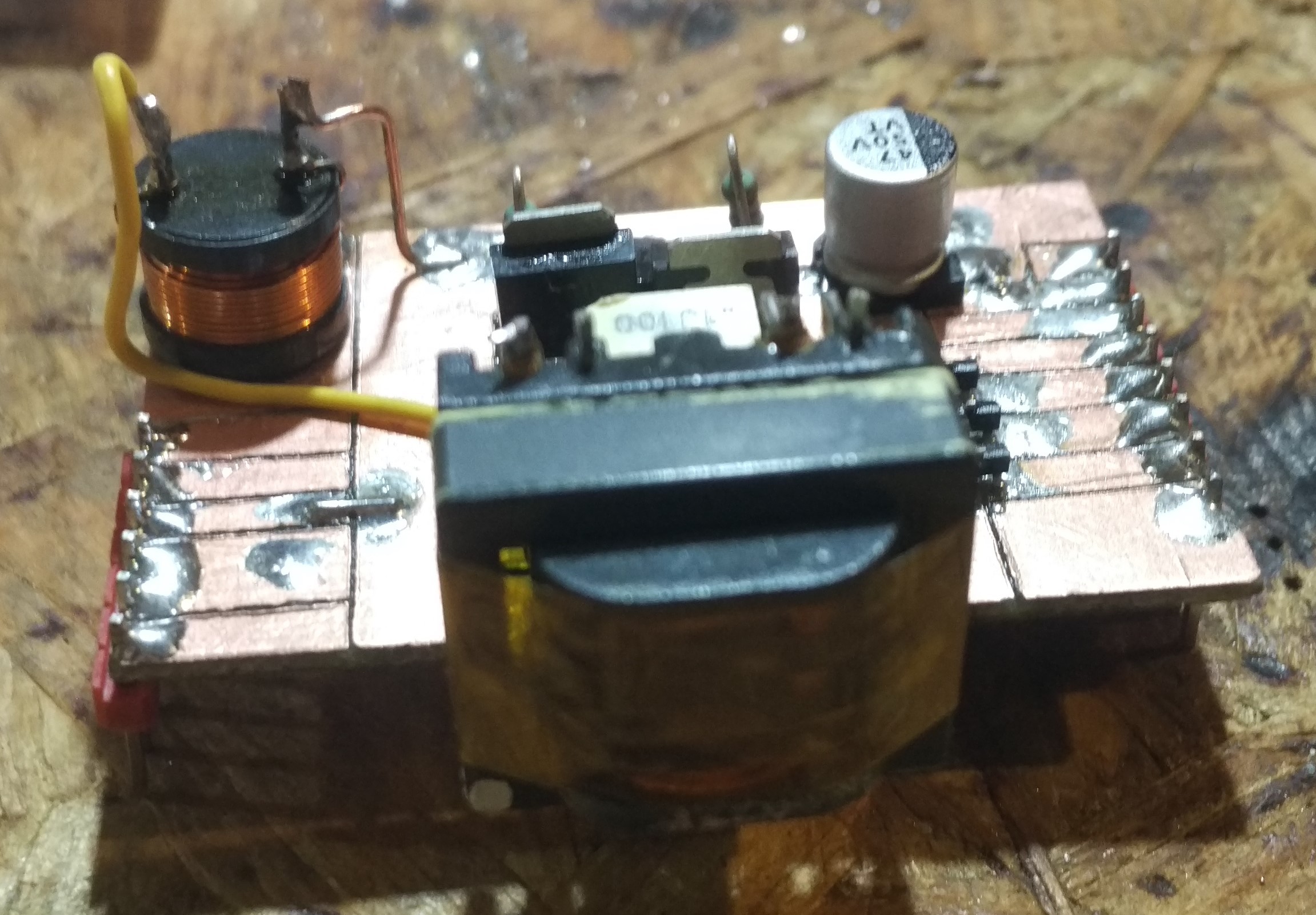
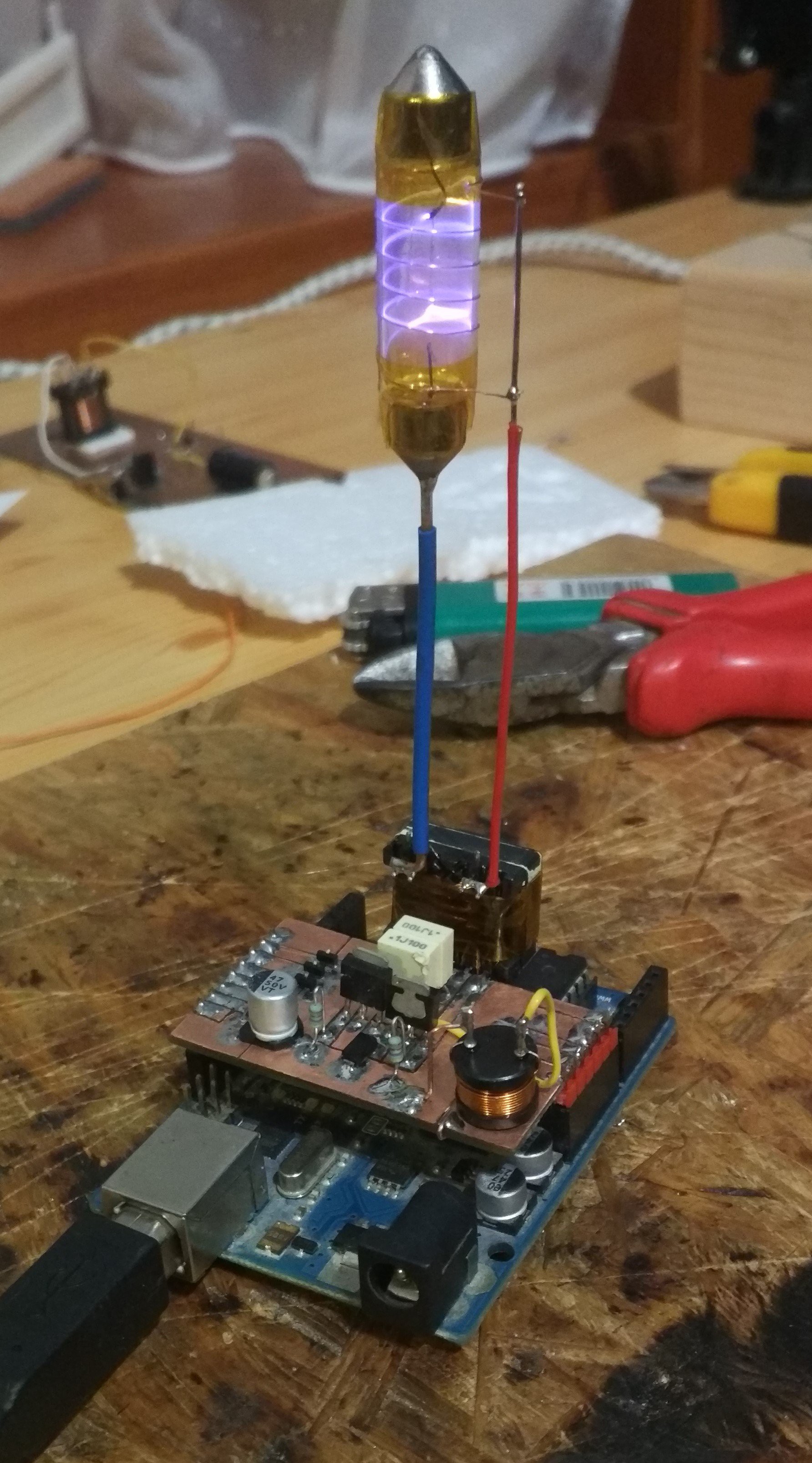
Then I soldered the components. I insulated the transformer with kapton tape, and soldered it at a 90 degree angle, so the HV side is upwards. This will hold the pillar to the tube. I also added a capacitor for extra buffer. The inductor wouldn't fit in the center, so I put it in the corner and used a wire to connect it to the transformer. I also added 3 P-channel MOSFETs to control the LEDs. These I removed later, as they were not needed, as it turned out.
 |  |
Using copper wires as pillars, I soldered the tube to the output of the transformer. Initially, I measured the current draw to be 870 mA, which is a bit much for the Arduino. By replacing the 1k pull-up resistors in the oscillator circuit to 4k7 ones, I managed to cut back the current to 470 mA. Good enough!
I plugged in the Arduino to USB, and it worked just fine. The result is... mesmerising.
Discussions
Become a Hackaday.io Member
Create an account to leave a comment. Already have an account? Log In.