Close
0%
0%

UBIRS

Ugly Bacteria Inspired Robot Sculpture. Search's for light while avoiding objects.

Similar projects worth following
In art, as well as electronics, inspiration can come from many different sources. For UBIRS I took inspiration from bacteria. While most of us try to avoid bacteria in general, the tiny little creatures are still fascinating. Tiny, simple single cell organisms that hunt food and duplicate: I think I can work with that. While UBIRS cannot replicate…at least not yet, it can search out light and avoid objects. UBIRS is designed to be as simple as possible. Two worm gear motors, each designed to run in one direction only. This creates a novel form of motion were the robot moves in a rotational fashion, as two photo resisters determine the direction of the brightest light. If either of two bump sensors detects an object, UBIRS goes into its panic mode, rapidly flashes its LEDs, and attempts to get around the object.

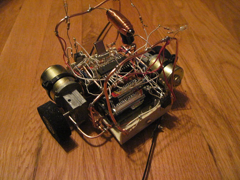
For the Circuit Sculpture Contest I wanted to create a project that was maybe a work of art (emphasis on maybe) but also a fun functional project. So UBIRS was born. To me, sometimes the beauty is not in the sculpture but in the sculpture in motion.

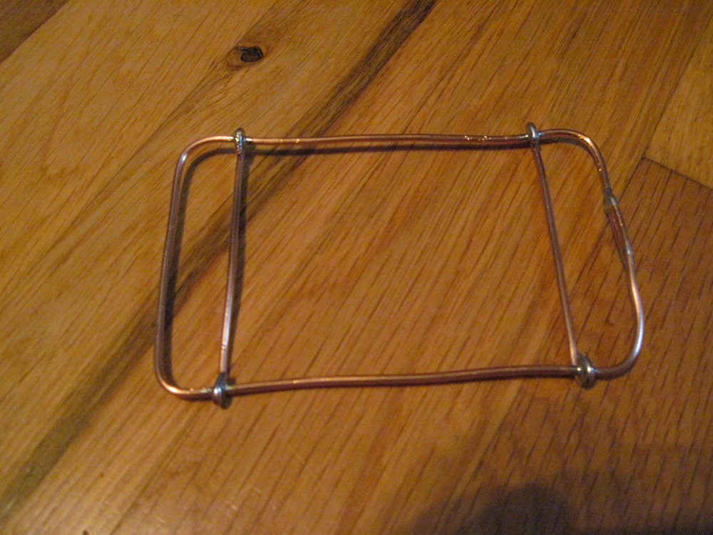
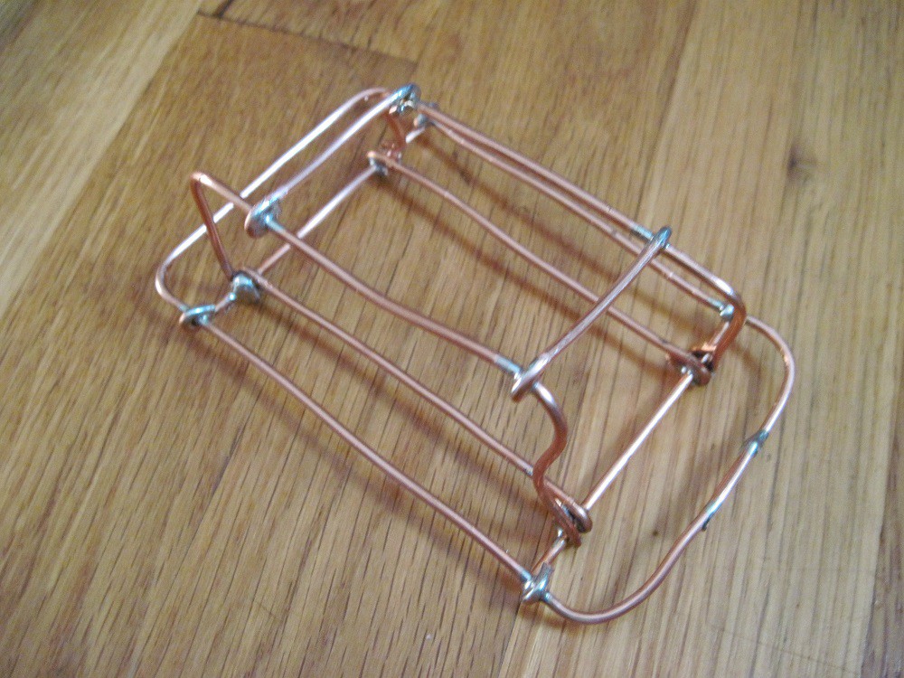
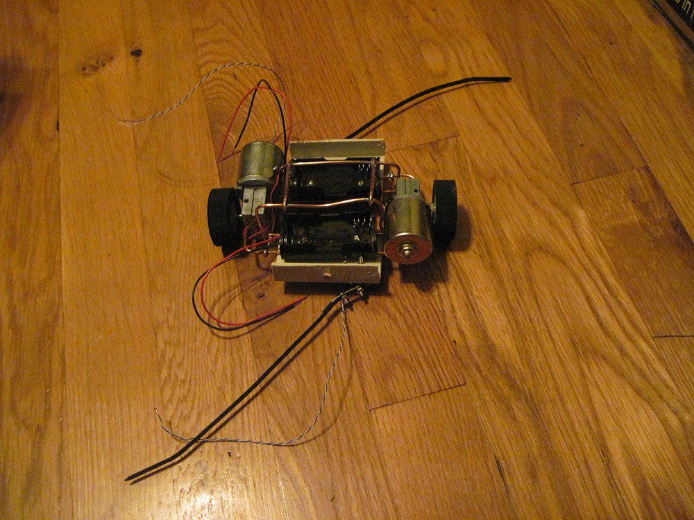
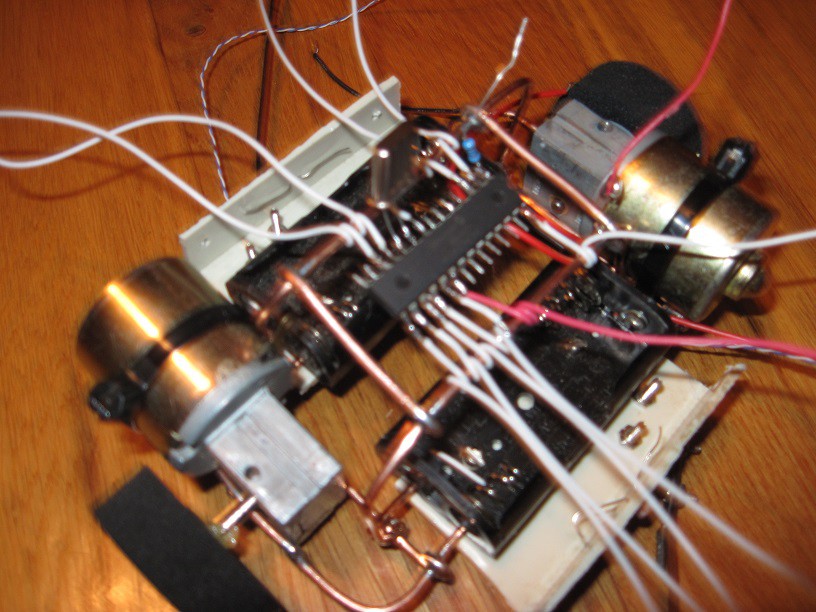
UBIRS is a bacteria-inspired robot sculpture based around a PIC16F873A micro-controller. To allow UBIRS to be as simple as possible, UBIRS’s two motors only turn in one direction.  Although not having bidirectional motion of the motors may seem like a disadvantage, it creates the opportunity for a more novel form of motion, which is a swirly rotary motion. This also allows only one transistor per motor instead of an h-bridge per motor. UBIRS is attracted to light and its main purpose in life is to avoid objects.  To accomplish this, UBIRS has two photo resisters, one on each side of the robot and two bump sensors, also one on each side of the robot.  UBIRS’s body is made of 14 AWG wires which I also wanted to be functional.  The copper wire frame is in three pieces. The bottom piece of copper wire frame is a common bus; the copper wire frame on one side of the bot is a positive bus, while the copper frame on the other side is a motor positive bus and is connected to the positive bus by an inductor and a 470 uF filter capacitor.  The busses are held together with two pieces of plastic which also provide a place for the battery holders, photo resisters and bump sensors.  UBIRS’s brain the PIC16F873A is suspended on the common bus.

ubirsr_main.c

UBIRS MAIN PROGRAM

plain - 2.37 kB - 12/31/2018 at 15:32

Download

  • 1 × PIC16F873A Microprocessors, Microcontrollers, DSPs / ARM, RISC-Based Microcontrollers
  • 2 × Worm gear motors
  • 2 × photo resisters
  • 2 × lever switch Switches and Relays / Switches
  • 1 × 14 gauge copper wire

View all 7 components

  • New Bot based on UBIRS!

    Dennis04/09/2019 at 01:11 0 comments

    I just added a new project based on UBIRS for The 2019Hackadayprize. Dustbot will be a new version that will use the same circular motion as UBIRS to sweep dust from hardwood and linoleum floors.    

  • UBIRS exploring a flashlight.

    Dennis12/30/2018 at 21:26 0 comments

    UBIRS finding and exploring a flashlight in a dark room.

  • UBIRS Schematic

    Dennis12/30/2018 at 04:27 0 comments

    The schematic shows the PIC16F873A and connections for the bump switches, photo resisters, Darlington transistors and motors.

View all 3 project logs

  • 1
    UBIRS assembly

    UBIRS started with a 14 AWG frame which also serves as the common bus.

    Next six more 14 AWG wires are soldered to the frame to serve as the PIC16F873A mount.

    Two plastic angles are added and photo resisters, battery holders and bump switches with two cable ties carefully bolted to them. The two motors are also pressed and tie wrapped into place.

    Add the PIC16F873A and solder wires to the PIC16F873A.

    Last install the positive 14AWG bus and the motor positive bus and solder the wires from the PIC16F873A to the photo resisters, bump switches, motors and the LEDS.

    Install an inductor between the two positive buses and add a filter capacitor between the motor positive bus and common bus.

View all instructions

Enjoy this project?

Share

Discussions

Similar Projects

Does this project spark your interest?

Become a member to follow this project and never miss any updates