Quinn
QuinnInspiration
I was inspired to create this work by a confluence of four events.
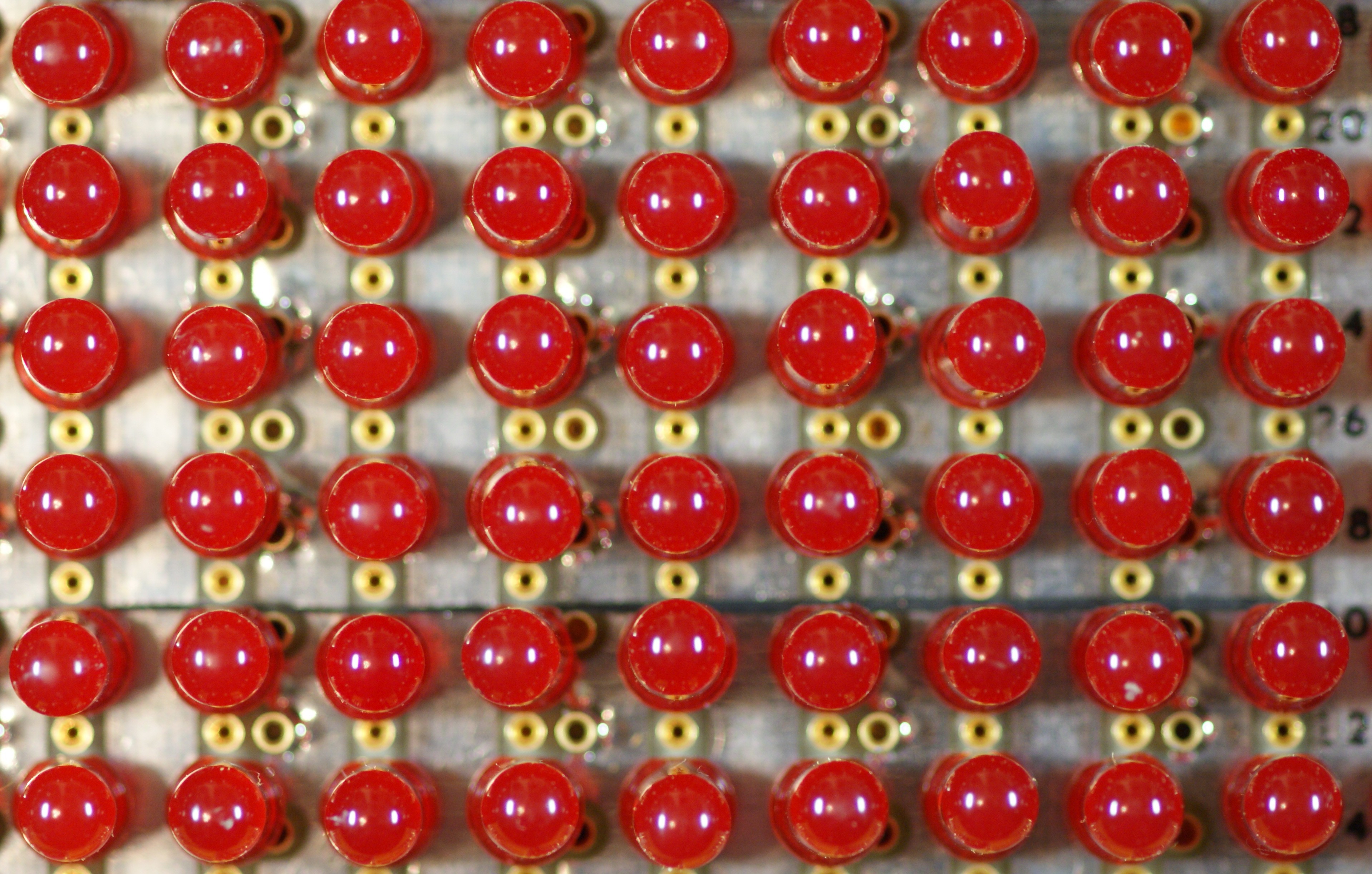
I had recently come across a discarded LED exit sign, made of individual 5mm red LEDs. They were easy to unsolder and I pondered for awhile what use I could put so many to.
A little earlier I had come upon a tube of DIP 74LS164 parallel out shift registers. Unlike the more common 595 shift registers, these do not have an output register, so the outputs show the shift register bits directly.
The project first found form from a rewatch of "War Games". Ever since seeing the movie, I found the scrolling random pattern on the side of the WOPR super computer mesmerizing.
The project found meaning from the relatively recent discovery of the accelerating expansion of the universe. I had recently learned about Linear Feedback Shift Registers and knew how well they could scale into massive numbers.
**Psuedo random
The core of the circuit is a Linear Feedback Shift Register. The 242 bit shift register is driven by an XNOR linear function of the current state. This forms a psuedo random number generator. While the output passes a number of the attributes of a random number, it is not truly random because it is repeatable and even reversible.
*Forever
A LFSR has a length, a number of counts in which it repeats. At the speed this circuit runs at, and the length of a 242 bit LFSR, it would have still not repeated it self if it had been started at the beginning of the universe, 13.7 billion years ago. So while mathematically it will repeat, even at the scale of the age of the universe, it will not. (ignoring the fact that the circuit will fail long before that)
When the accelerating expansion of the universe was discovered in 1998, we went from believing we were in a universe which had a time limit, to a universe which did not. I found the interplay interesting between that and the idea of a random number which never repeats, but mathematically will. There is a duality of infinite and finite in these concepts that I think brings meaning to the work.
Circuit
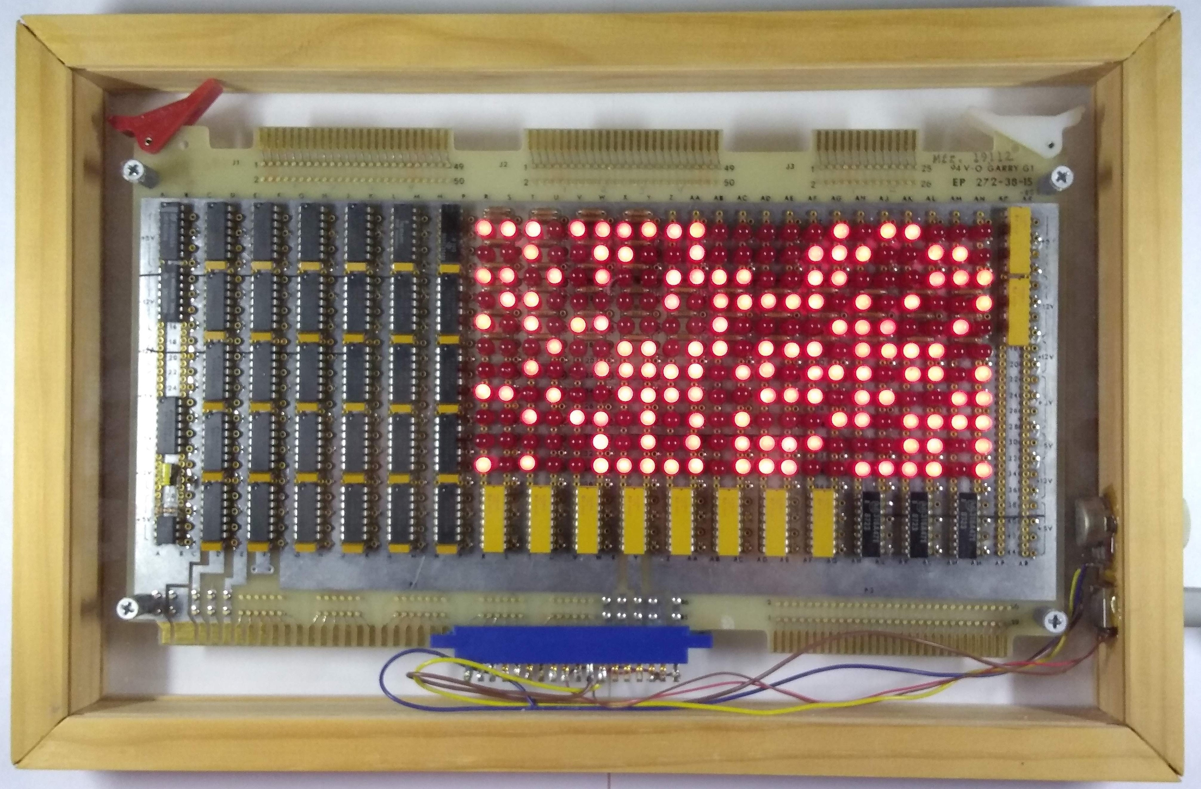
The entire design is done with discrete logic gates, LEDs and resistors. It runs on a single 5V rail. As the LEDs can all be on at the same time, current can be as high as 1.5A. Given the random nature of each bit, most of the time the current will be half that.
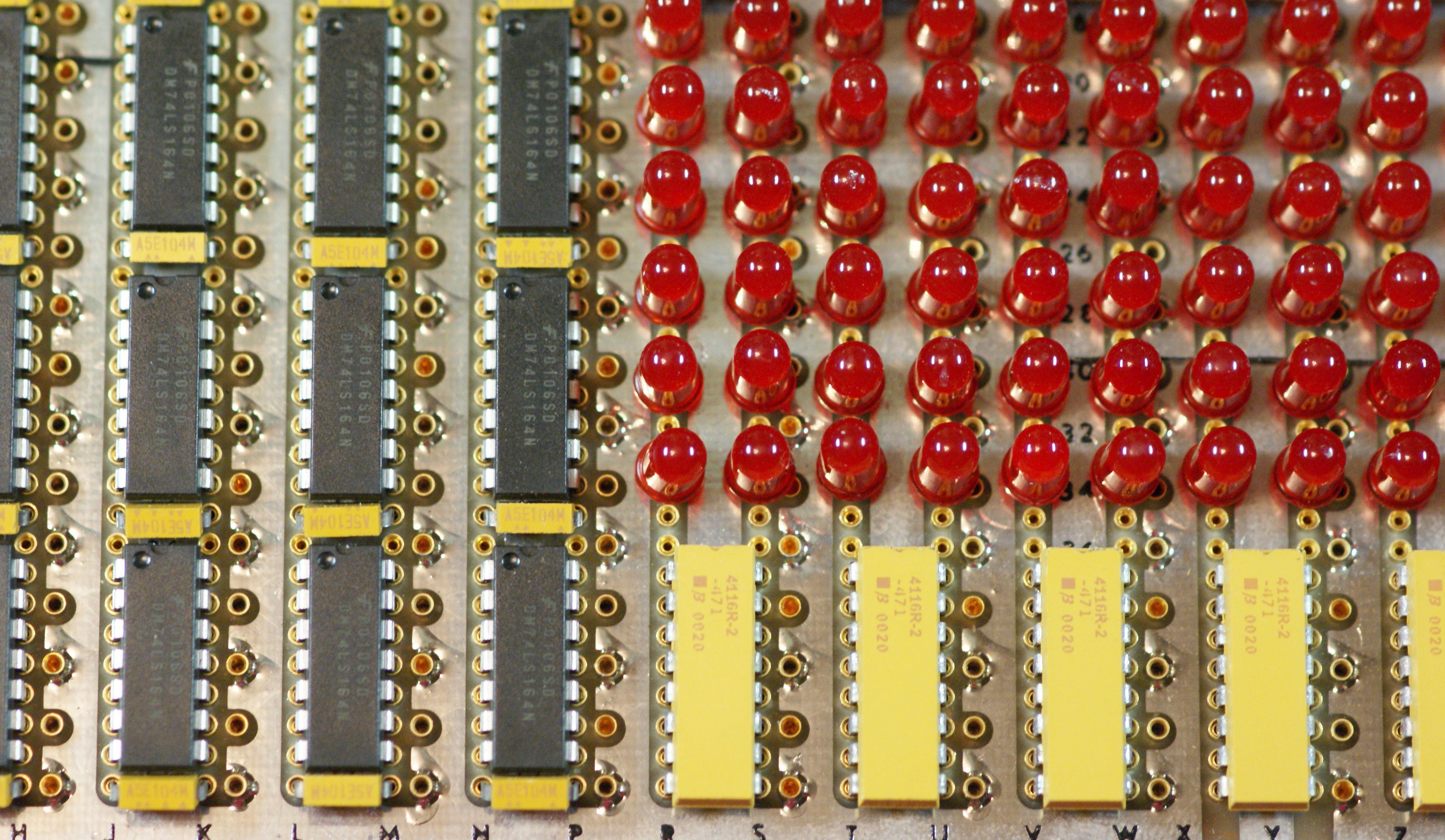
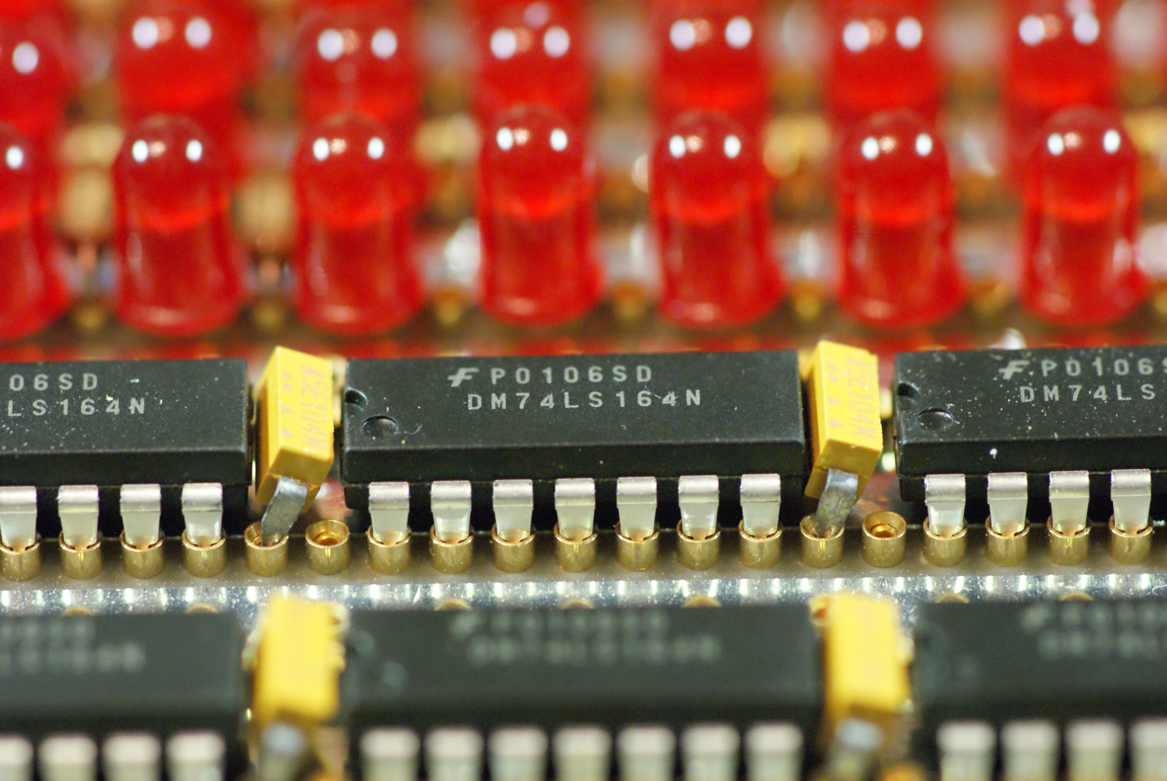
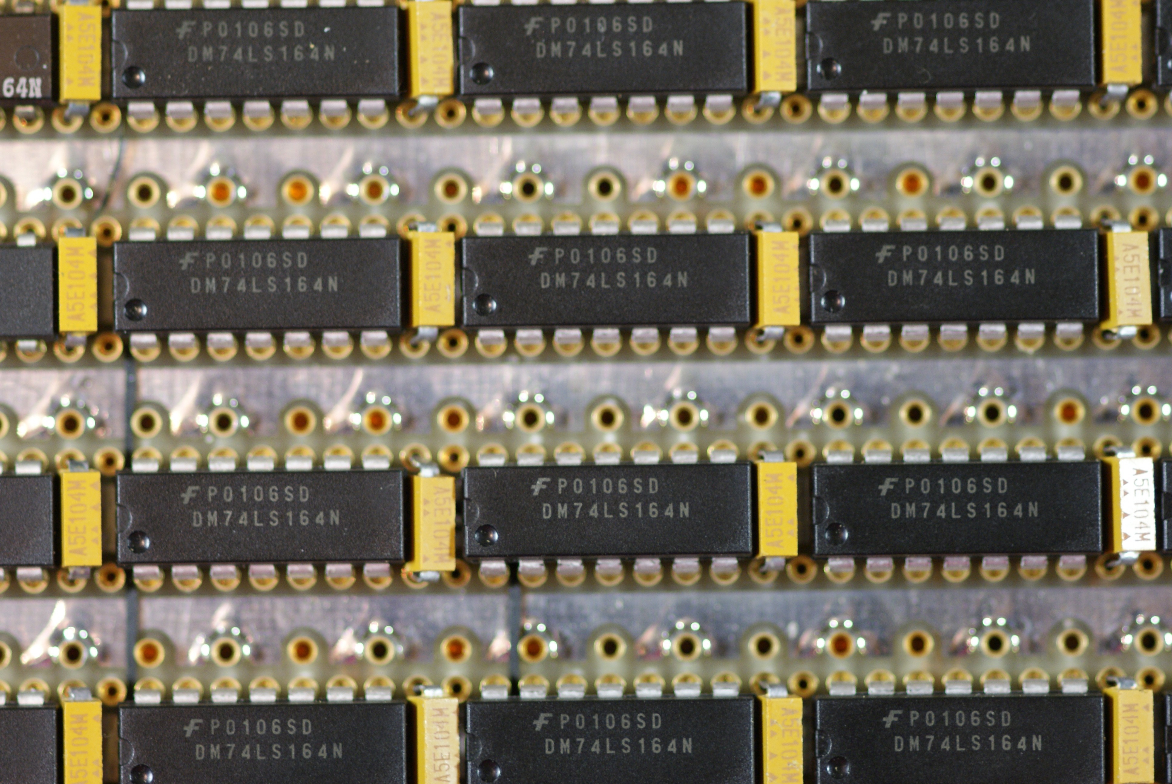
This shift register is made of 31 74LS164 shift registers, each device cascaded into the next, with a common clock to all devices. The parallel outputs of the shift registers drive the LEDs directly. That is, this is not an LED matrix; there is no scanning or microcontroller driving them.
A 74S86 XOR chip is used to form the feedback function, with it's output passed through a 74S04 inverter to function as an XNOR. Extra gates in the 74S04 and 74S86 chips were used as buffers for the clock.
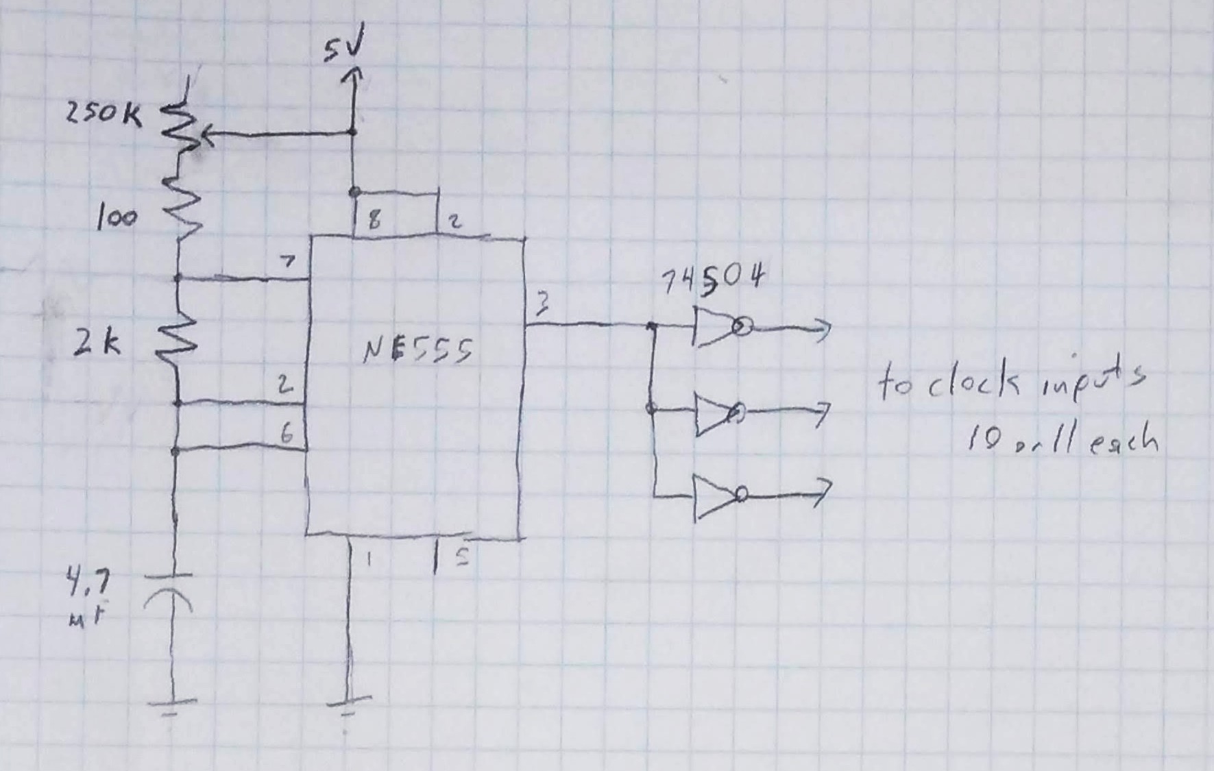
A 555 timer circuit is used to clock the shift registers allowing a user adjustable potentiometer to change the clocking speed from about 0.5Hz to 20Hz.
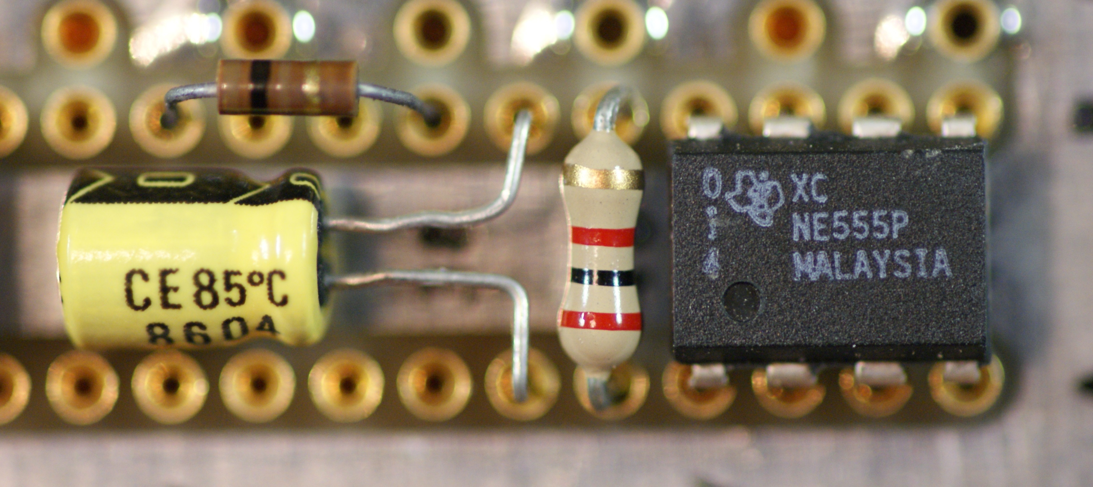
The output pins of the shift registers go to the LED cathodes, while the LED anodes pass through a 470 ohm resistor to the 5V rail. Most of the resistors are in DIP resistor networks to save space.
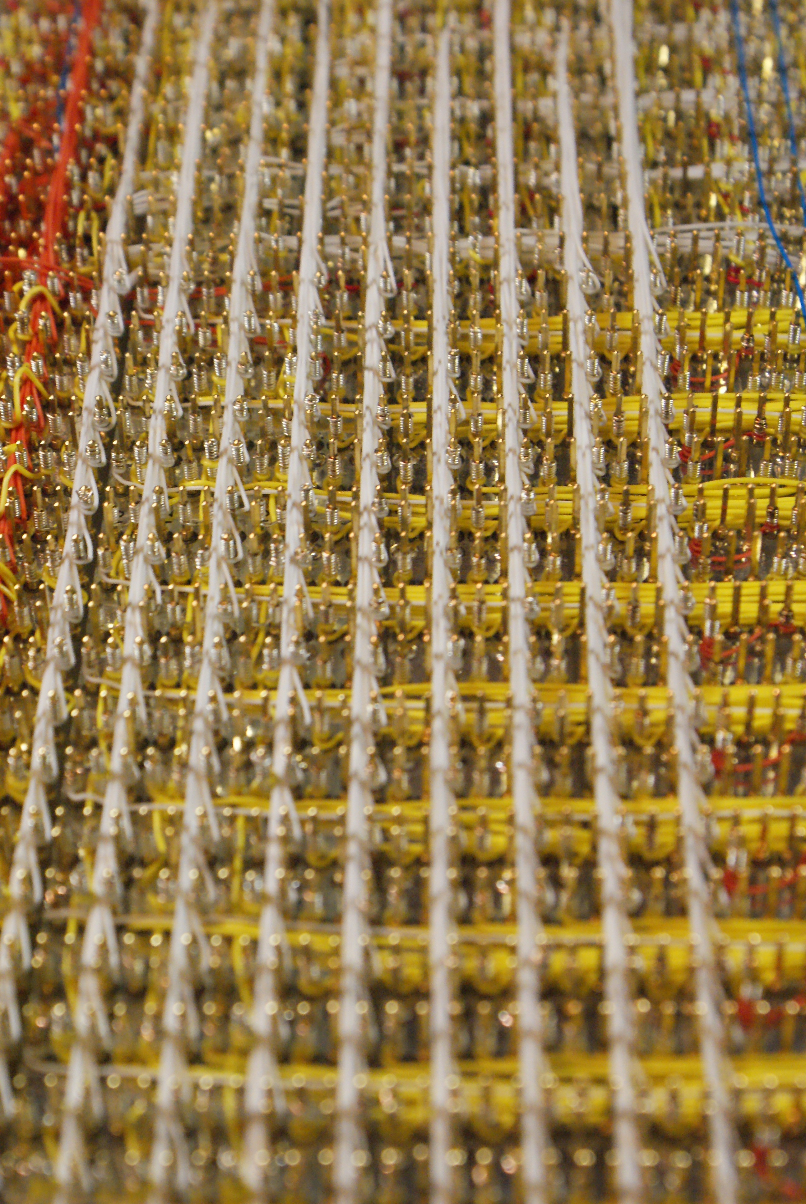
Wiring
An intentional part of this work was to wire it not by making a PCB, but by creating an interesting pattern in wire wrap circuit construction. This circuit has an estimated 1500 connection points, all done without solder. 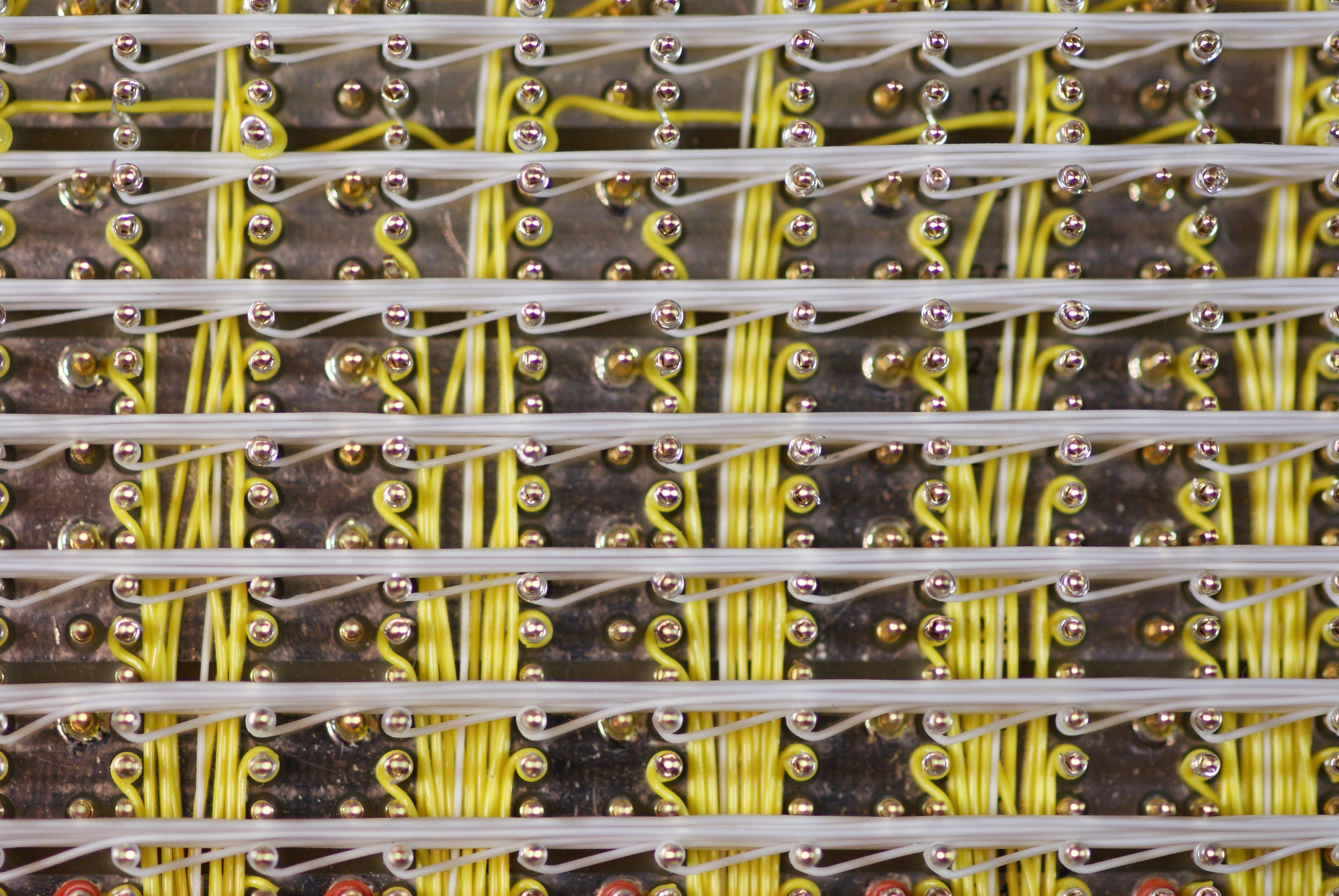
The base PCB is a special kind which was manufactured with an array of wire wrap pins and sockets in DIP spaced rows across the entire board. To use the board, you simply insert the components in any socket position you want, and wire accordingly on the back side.
Update: fellow hackaday.io user Mel found the project interesting and did some research on the wire wrap board I used. I recall pulling it out of an old custom computer I purchased from a university surplus sale, and had guessed it was from the 80s but didn't recall the details as I had disassembled it long ago. It turns out this is a board for an Intel SBC 80/10 system. You can see an advertisement for this board from 1977 on magazine page 79 here. No idea the cost, but with over 1600 gold plated machined type socket pins, I'm sure it wasn't cheap.
It occurs to me in thinking about this, that the entirety of the circuit is built with parts made before 1998, adding a little extra relevance to the this project and that discovery of the accelerating expansion of the universe.
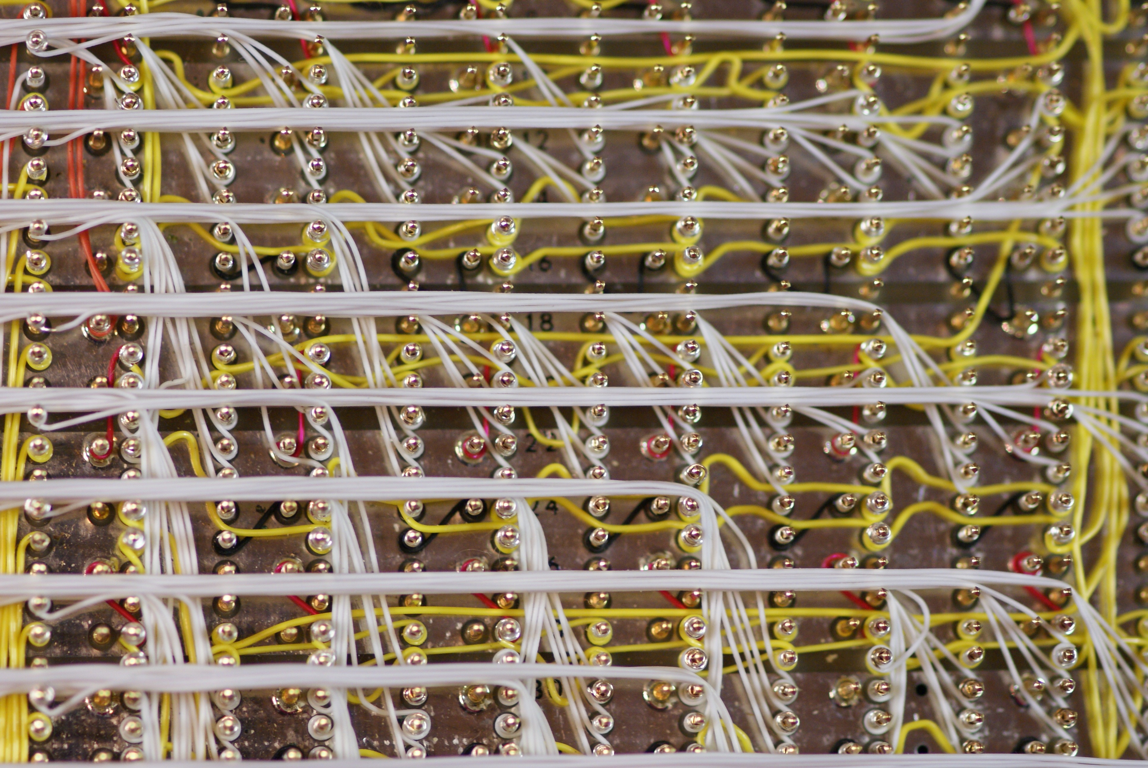 The result is a back side which is a mix of uniform lines and pattern, but differences and variations in the pattern seem to be random with unclear meaning.
Frame
I constructed a custom wood frame with plexiglass front and rear to allow both sides of the work to be seen. The frame is simple 1x2 material with a dado at the front for the fixed plexiglass, and a dado at the back with screws holding one side it that allows the rear plexiglass to be removed. Overall it measures 9.5 by 14.25 by 1.5 inches
The clock speed adjustment potentiometer and the DC power socket are embedded into the frame.
Schematics
This was designed and built without creating schematics. While it involves a lot of parts, it is really just some basic circuits used over and over. By request, I did draw out some simplified diagrams.
Here is the 555 circuit used to create the low frequency adjustable clock. Two of the 3 buffered outputs go to 10 of the 74LS164 chips, while the third goes to 11 of them. The 100 ohm resistor in series with the potentiometer is there so that at the end of the potentiometer's travel there is still a minimum resistance.
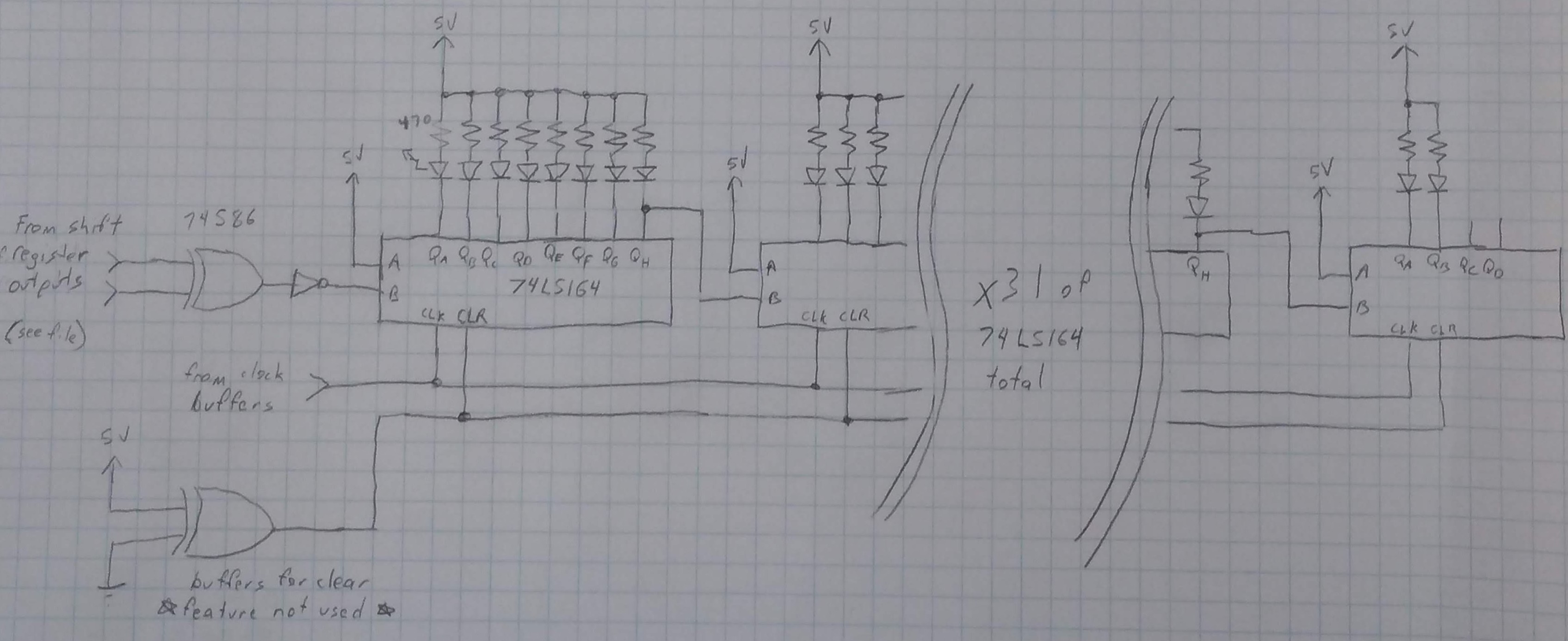
Here is a diagram of the shift registers. As the circuit just repeats, I've shown only the beginning and the end. Vcc and Gnd are not shown, but all connected. This simplified diagram also shows a single common clock line and clear line, while these are actually broken up into groupings of 10, 10 and 11. The clear line was implemented, but not required as the registers seem to always power up mostly 0, preventing the lock up case of all 1's in the register. The inputs to the XOR gate are fed from taps in the shift register chain. See the attached file for different tap values to use for different shift register lengths.