 Quinn
QuinnInspiration
I was inspired to create this work by a confluence of four events.
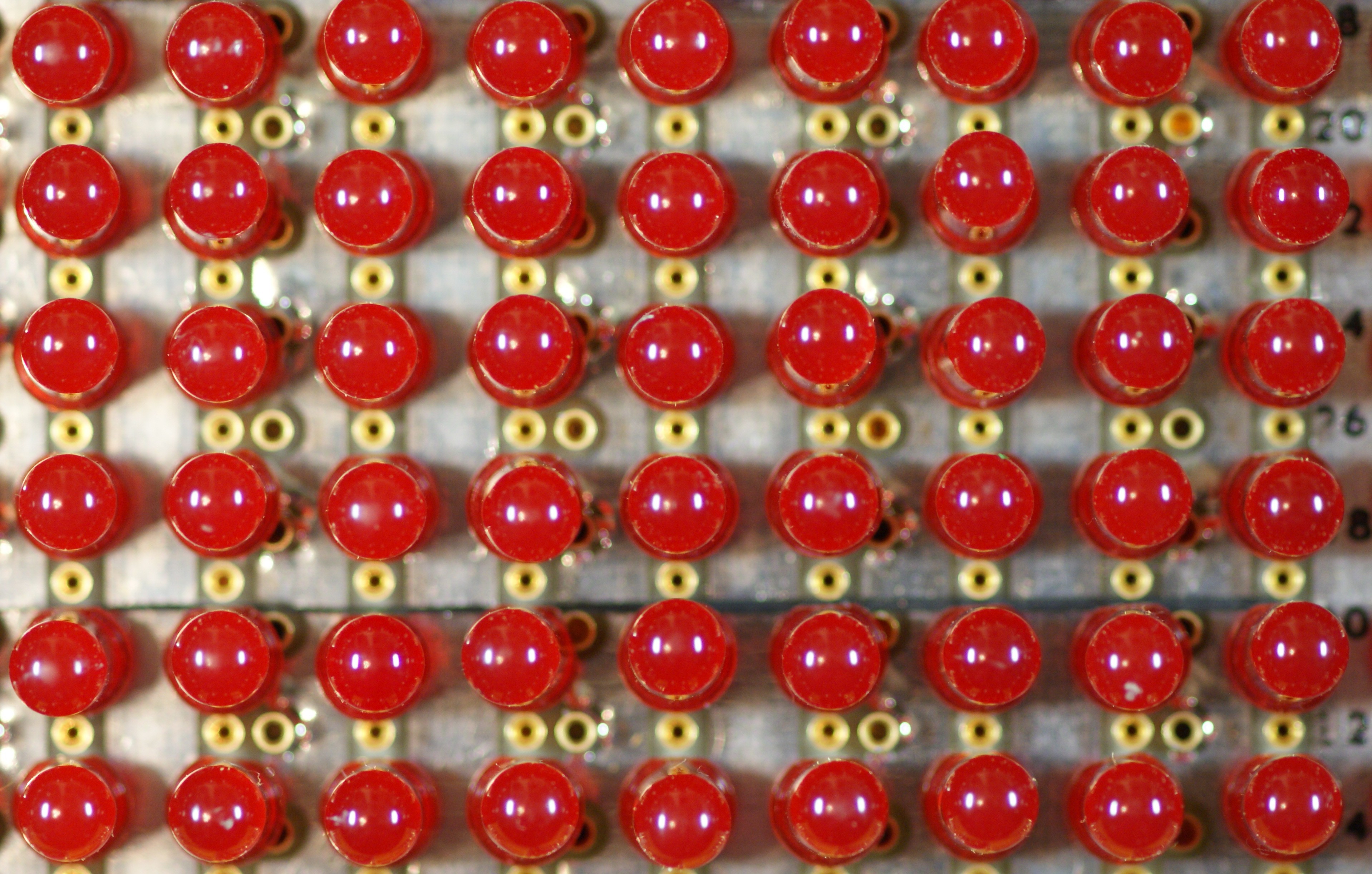
I had recently come across a discarded LED exit sign, made of individual 5mm red LEDs. They were easy to unsolder and I pondered for awhile what use I could put so many to.
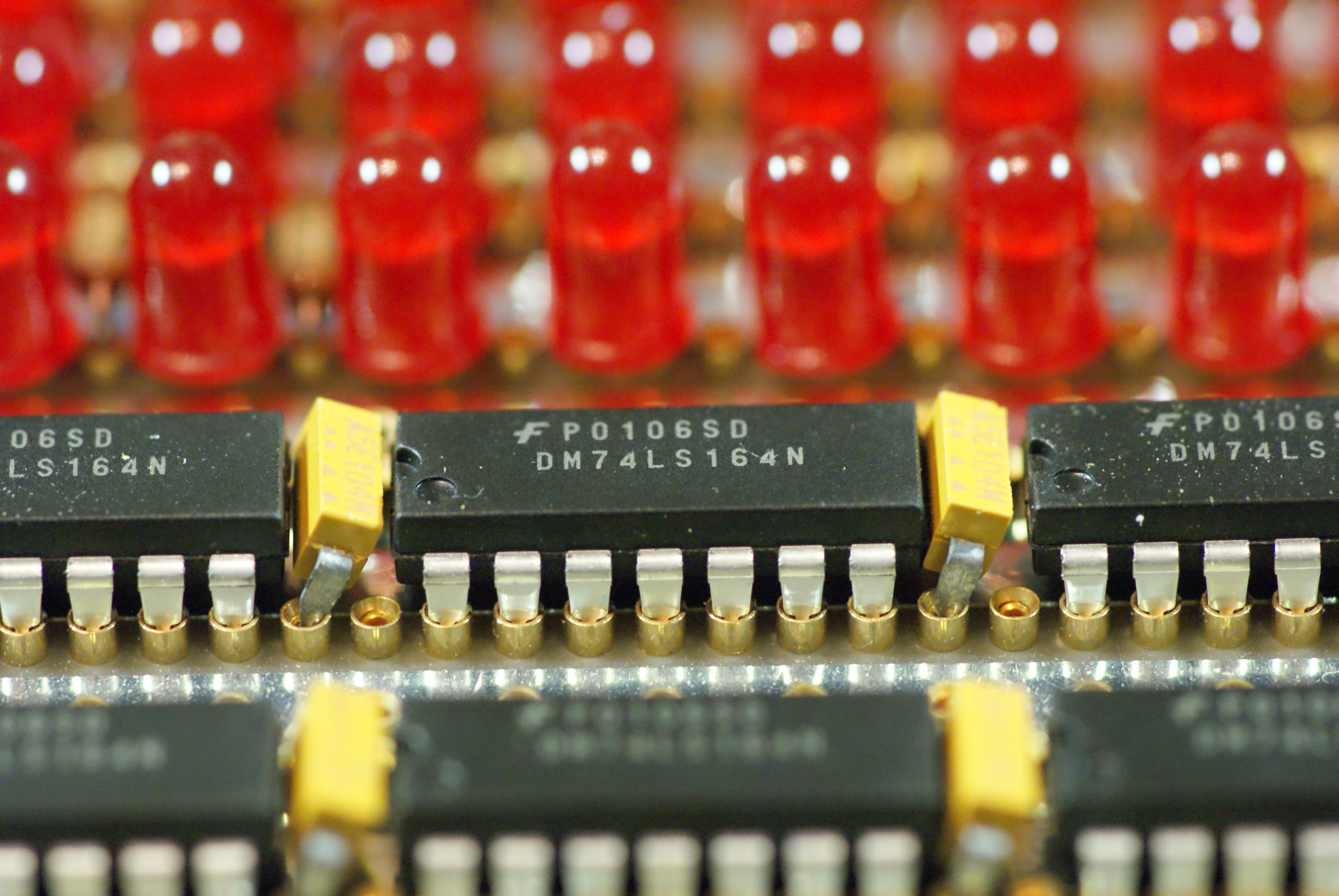
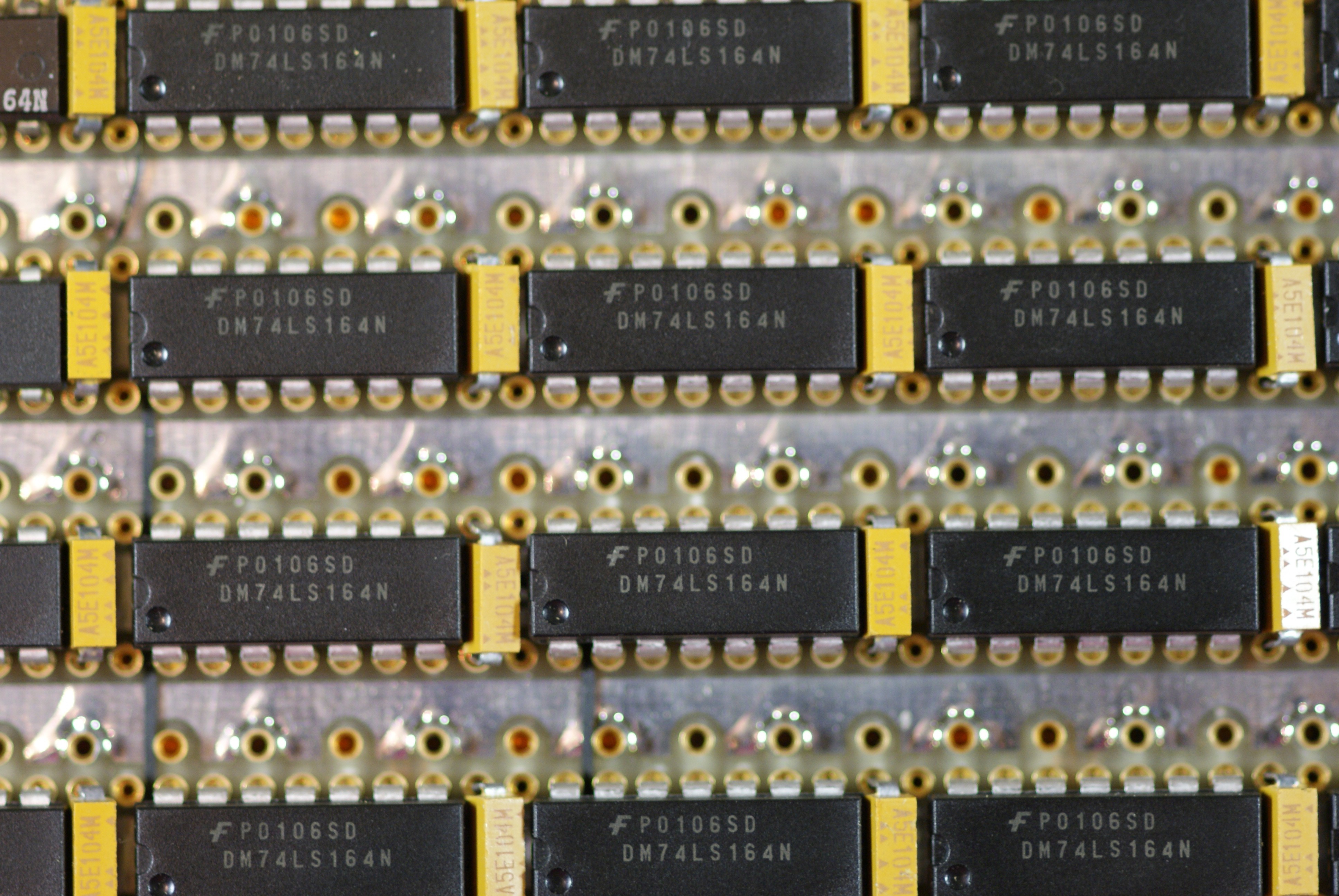
A little earlier I had come upon a tube of DIP 74LS164 parallel out shift registers. Unlike the more common 595 shift registers, these do not have an output register, so the outputs show the shift register bits directly.
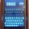
The project first found form from a rewatch of "War Games". Ever since seeing the movie, I found the scrolling random pattern on the side of the WOPR super computer mesmerizing.
The project found meaning from the relatively recent discovery of the accelerating expansion of the universe. I had recently learned about Linear Feedback Shift Registers and knew how well they could scale into massive numbers.
**Psuedo random
The core of the circuit is a Linear Feedback Shift Register. The 242 bit shift register is driven by an XNOR linear function of the current state. This forms a psuedo random number generator. While the output passes a number of the attributes of a random number, it is not truly random because it is repeatable and even reversible.
*Forever
A LFSR has a length, a number of counts in which it repeats. At the speed this circuit runs at, and the length of a 242 bit LFSR, it would have still not repeated it self if it had been started at the beginning of the universe, 13.7 billion years ago. So while mathematically it will repeat, even at the scale of the age of the universe, it will not. (ignoring the fact that the circuit will fail long before that)
When the accelerating expansion of the universe was discovered in 1998, we went from believing we were in a universe which had a time limit, to a universe which did not. I found the interplay interesting between that and the idea of a random number which never repeats, but mathematically will. There is a duality of infinite and finite in these concepts that I think brings meaning to the work.
Circuit
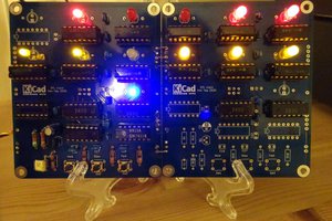
The entire design is done with discrete logic gates, LEDs and resistors. It runs on a single 5V rail. As the LEDs can all be on at the same time, current can be as high as 1.5A. Given the random nature of each bit, most of the time the current will be half that.
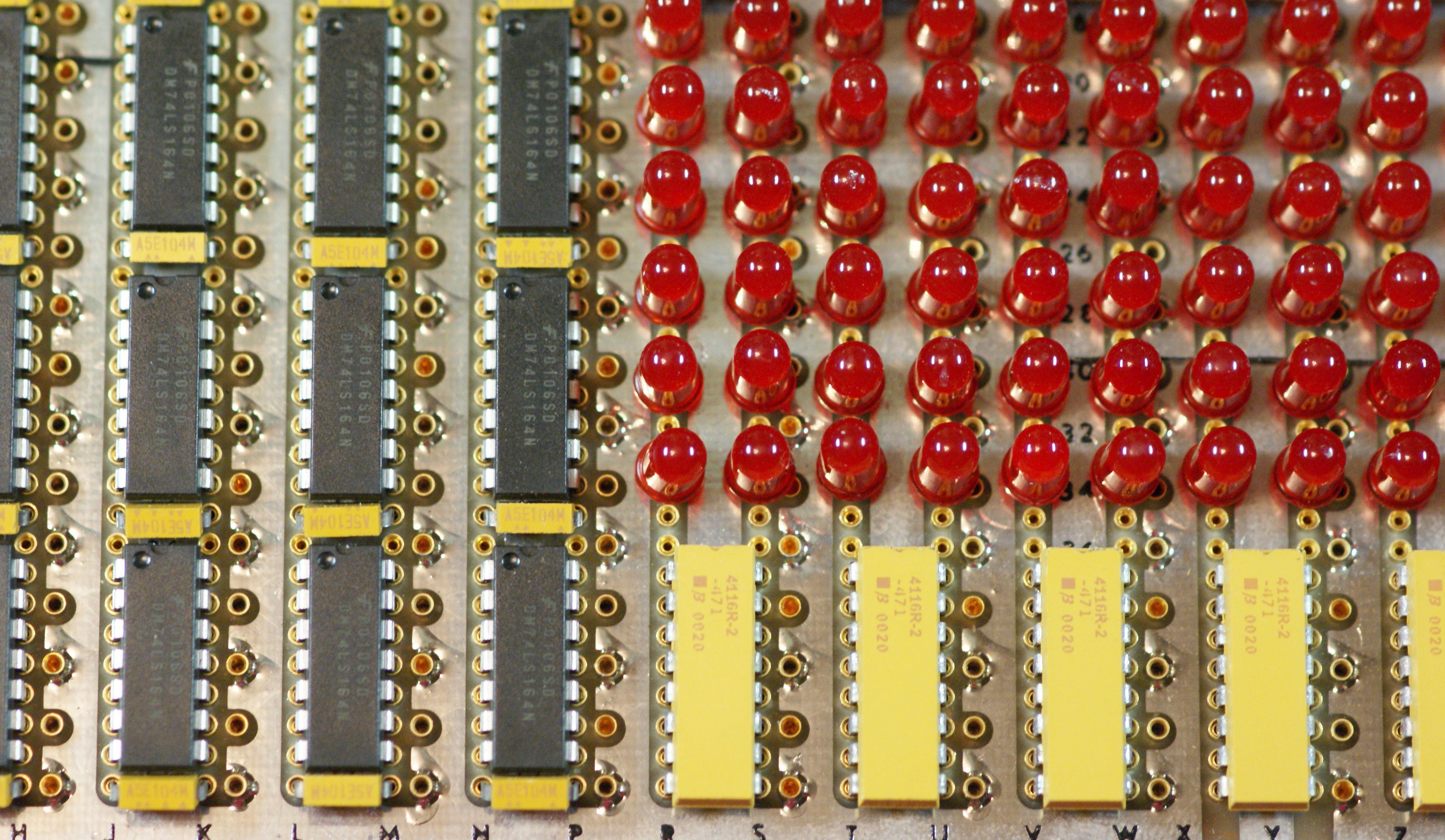
This shift register is made of 31 74LS164 shift registers, each device cascaded into the next, with a common clock to all devices. The parallel outputs of the shift registers drive the LEDs directly. That is, this is not an LED matrix; there is no scanning or microcontroller driving them.
A 74S86 XOR chip is used to form the feedback function, with it's output passed through a 74S04 inverter to function as an XNOR. Extra gates in the 74S04 and 74S86 chips were used as buffers for the clock.
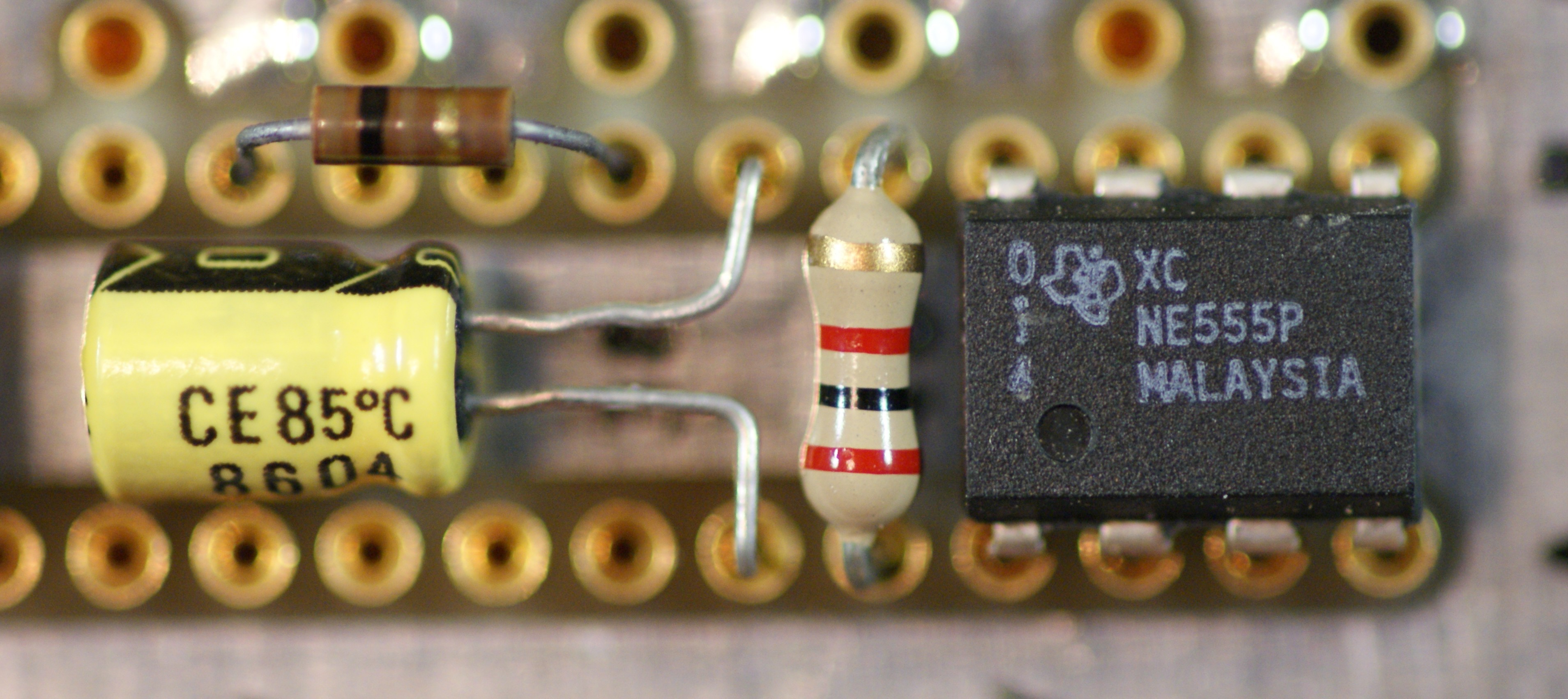
A 555 timer circuit is used to clock the shift registers allowing a user adjustable potentiometer to change the clocking speed from about 0.5Hz to 20Hz.
The output pins of the shift registers go to the LED cathodes, while the LED anodes pass through a 470 ohm resistor to the 5V rail. Most of the resistors are in DIP resistor networks to save space.
Wiring
An intentional part of this work was to wire it not by making a PCB, but by creating an interesting pattern in wire wrap circuit construction. This circuit has an estimated 1500 connection points, all done without solder. 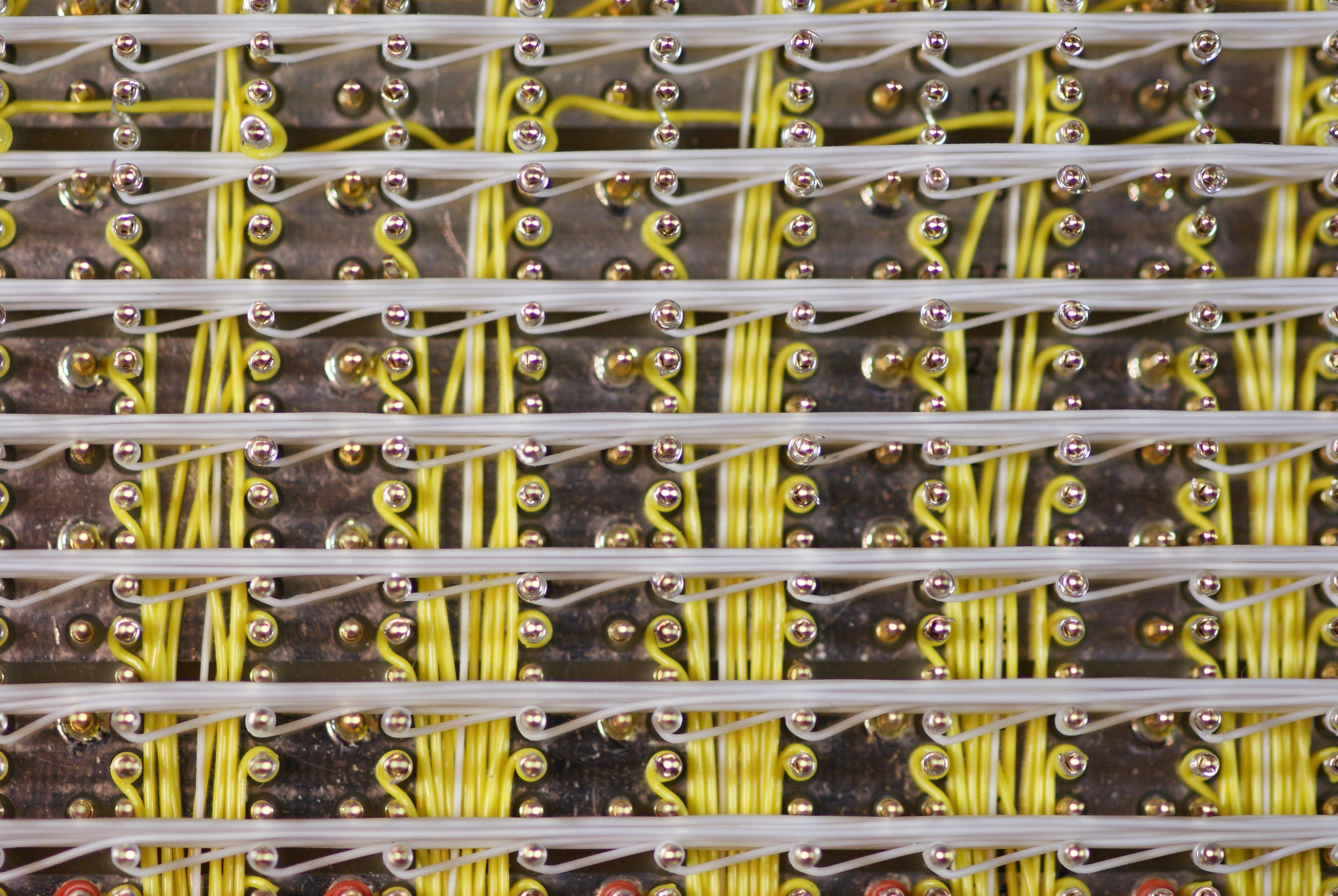
The base PCB is a special kind which was manufactured...
Read more »


 Ken Yap
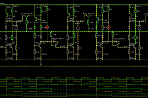
 Yann Guidon / YGDES
 Tim
Tim
 Dave Gönner
Any large scale use of leds gets my two thumbs up vote :-) I doubt that I will try to replicate this with my Light Logic. Hats off to your work :-D