 Laetitia BEL
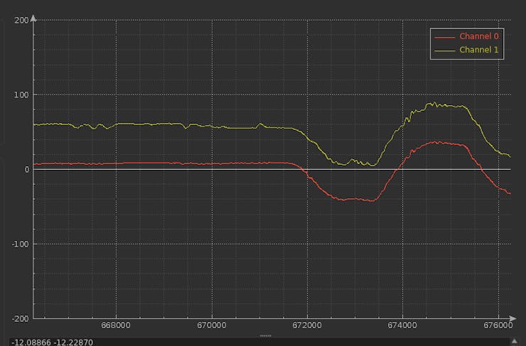
Introduction
In this project, I describe my small odyssey in Ada for embedded ARM to realize from scratch an redundant IMU software and harware environment based on the latest performant IMU, the BMI088. And how to estimate the pitch and roll:
What I want to do, is to be able to control and process a redundant IMU088 (with 13x IMU) to get the best possible result in high vibration environment, an amateur rocket and high precision drones.
For that am using the AdaCore framework and toolchain to benefit from the robust coding environment that they offer highly recognized in safety/reliability oriented industries. Specially for someone who isn't pro in embedded systems using C, not mastering the "savoir faire" of the C can be a headache.
I noticed during the code realization that the Ada code and speclialy the one editied in AdaCore GitHub repo is easily readable.
For someone, like me, who is used to C/C++ and java environment, it wasn't exceptionnaly hard to put the hand on the Ada. Specially that it reminds me Pascal and Caml that I used in very past.
The Super has been developed to be used in amateur rockets for CNRS Planete Science competitions. It will help computing precise attitude in a high vibration environment to stabilize the rocket during the flight using the ailerons.
The SuperIMU has to be embedded in a lancer with a core diameter less than 90mm.
Step 1: System description
The SuperIMU has 13x redundant 6DoF IMU, it can fit in 50mm diameter. It also embeds a compass and barometer which are not redundant.
It will communicate with the microcontroller using the SPI interface to get raw data (accel and gyro data).
We use a simple architecture to visualize and test the SuperIMU:
The SuperIMU sends the raw acceleration/gyroscope rates to the microcontroller using the SPI port.
The microcontroller filter the raw data, and estimate the angles. It sends the angles values using the UART port for analysis purpose.
The UART port is connected to the computer to visualize the data using a serial to USB module.
When tests are satisfying, I will create a specific hosting board for the SuperIMU. The hosting board will be circular using the STM32F746 microcontroller.
The IMU will be distributed as folowing, in a star shape:
The angular distribution follows a 45° pattern:
The previous pattern has been selected to maximize the presence of IMUs over the surface to be able to vary the sensing range.According to a geometrical study conducted in Texas University (Redundant IMU Configurations : paper) where different geometrical configurations:- the geometrical the distribution in a 3D space of the sensor as better results than a distribution on a plan (our case)-- no impact on the accleration (aDOP Accelaration Dilution of Precision)-- impact on the rotation precision (wDOP Angular Dilution of Precision)-- impact on the geometrical precision dillution- the more IMU we add, the more precision we have- the orientation of the IMU doesn't have a significant impact on the result
We keep this study in mind, to reach a cube like configuration we can put two SuperIMU in parallel.For the moment we continue in Unit Circle configuration an try to get the maximum from it.
Sensitivity range configuration: rocket mode
In an amateur rocket the acceleration can reach 8 to 9g during the first seconds of flight.
Here is a typical flight log (acceleration/velocity) of an amateur rocket with the three phases (propulsion, ascending without propulsion, chute opening, diving with chute, earth contact):
During the short flight, the typical acceleration profile is like following:- launching <7 seconds : acceleration >6g- ascending without propulsioin <11s before parachute opening: <3g- diving with parachute <50s : <3g
The sensing range needs to be tolerant to both low and high during the flight to have a precise control. The IMU during will be configured...
Read more »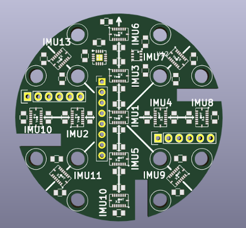
 Alex Hunt
 Bharbour
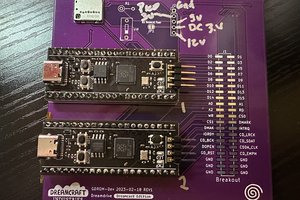
 Kaili Hill
Could you collect data from 13 IMUs in parallel? Did you calibrate IMUs?