 Darren V Levine
Initial Work:
Log update: 01/05/2019
As a first step I built a Port-Hamiltonian simulation framework in MATLAB, in order to teach myself the low-level math/physics. It turned out to be extremely slow, and so I could only use it for 2D sims. Here is my first attempt at a low-cost heuristic based stabilization controller (very Monty-Python-esc I know).
More recently I've moved to an articulated body Featherstone simulation framework in MATLAB. Here is another even simpler heuristic based control scheme:
Eventually I'll work on efficiency and stability, but for now this does have the advantage of being naively extensible to arbitrary N-Jointed x N-Limbs without a training period. My next steps are to progress more on the hardware end in order to test any controllers on actual hardware.
On the hardware end, I made many many early mistakes, including under-sizing motors and components. I created a small 3d-Printable 9:1 planetary gearbox that overlays each motor which fixed that issue:
Here is a video of an early prototype leg:
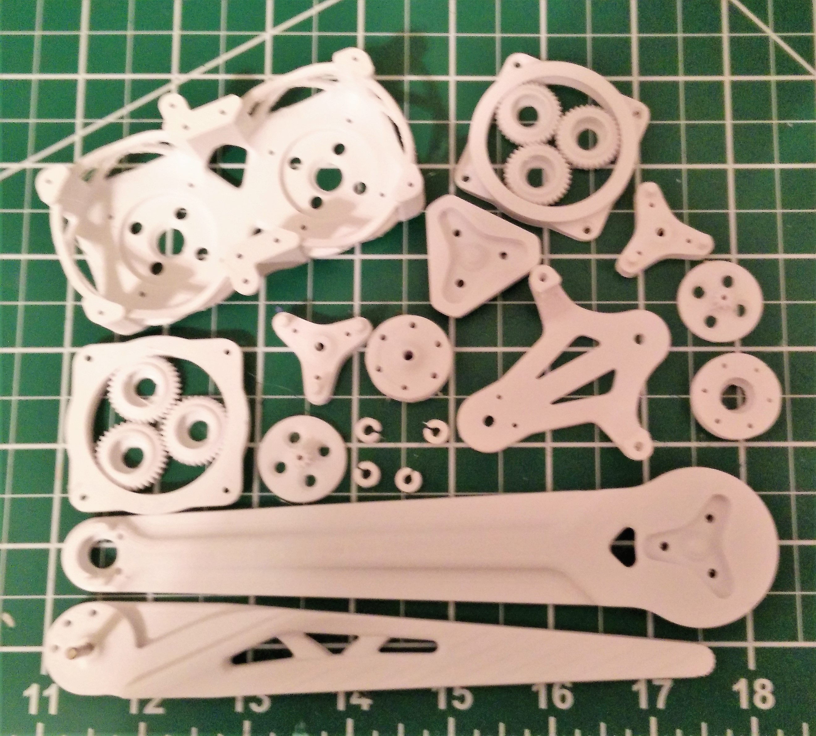
The cable design turned out to be very difficult to work with and produced unnecessary strain on the motor housing, so I moved to a belt/gear design even though it adds weight. The 9:1 planetary 3d-printed gears also needed a redesign to produce better printer yields. The next iteration included more robust components, though it was far from a final design. Producing such small parts in order to try and conserve weight and size means I'm always finding new bottlenecks that need to be fixed.
Reducing lashing in leg/hip:
Log update: 02/09/2019
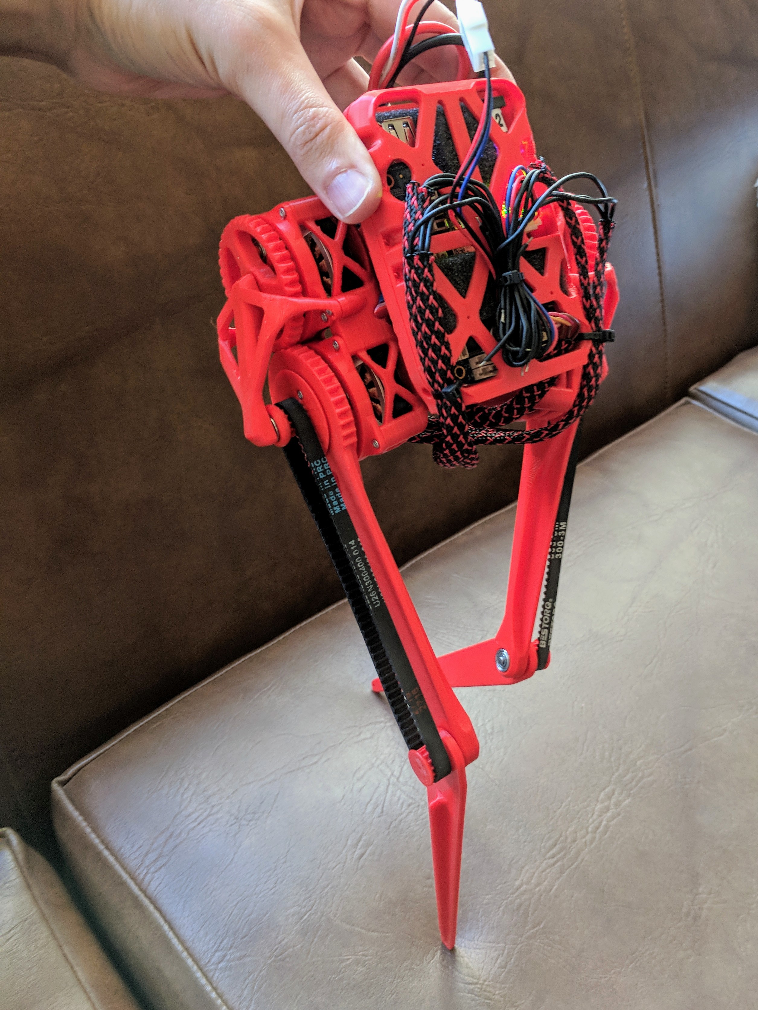
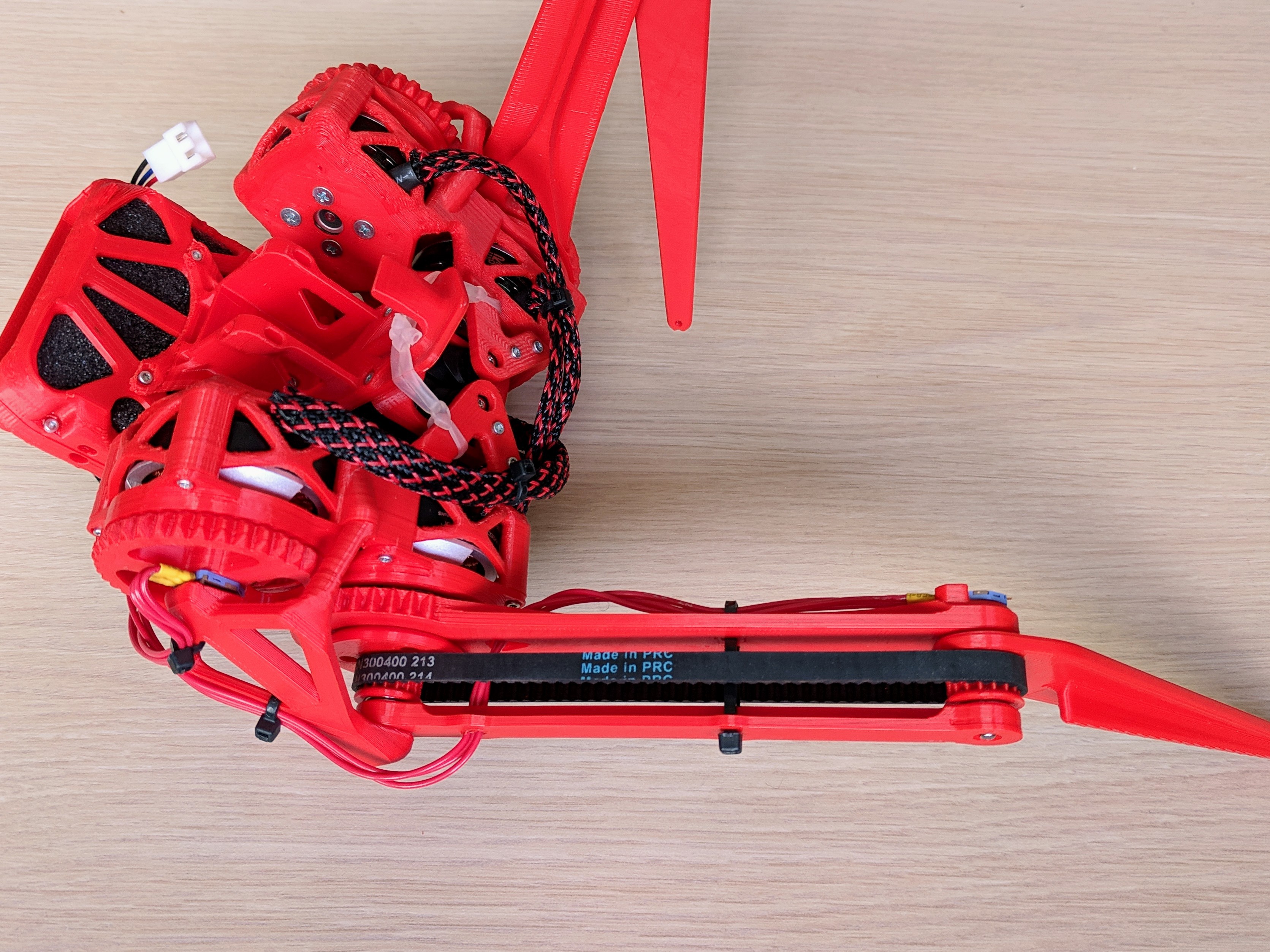
I updated the leg design with slightly thicker limbs and added a supportive bar on the external femur. The extra bar allows the belt to be tightened down significantly more, reducing play to a much more acceptable level. Here's a picture of the new leg all assembled and instrumented:
Other progress:
I'm did some more work to improve yield issues with the very small planetary gears on each motor (the teeth are the width of my printer's nozzle), in particular upgrading my 3D printer's firmware last weekend helped a bit. Although it is time consuming, a few more iterative tweaks are probably in order. Not having to resort to metal gears will be a huge cost/time saver in the final product.
I'm using 333 degree potentiometers on each joint instead of encoders to significantly reduce cost and size. They produce a single analog signal that needs ADC sampling and kalman filtering (due to reduced performance in vibration). At the moment, I'm doing that in software on the beaglebone (located on the back of the robot), which works decently well. So, I'm hopeful this cut-corner will work out. However, I'll now need to either convert that signal to one compatible with the Odrive's discrete encoder inputs, or modify the Odrive's firmware to do the job. Still more tinkering to do on that front.
As for the idea of building my own motor controller, after looking at the various resources and designs available such as Ben Katz's: http://dspace.mit.edu/handle/1721.1/118671#files-area, I'm both more excited about making a custom board, and more aware of how large of an endeavor it would be ( VESC (Best Open Source ESC) || DIY or Buy). So, I'll likely do it as a separate project once I'm happy with TipTap's base model platform.
That's it for now. Thanks for looking!
Discussions
Become a Hackaday.io Member
Create an account to leave a comment. Already have an account? Log In.