Hi Everyone,
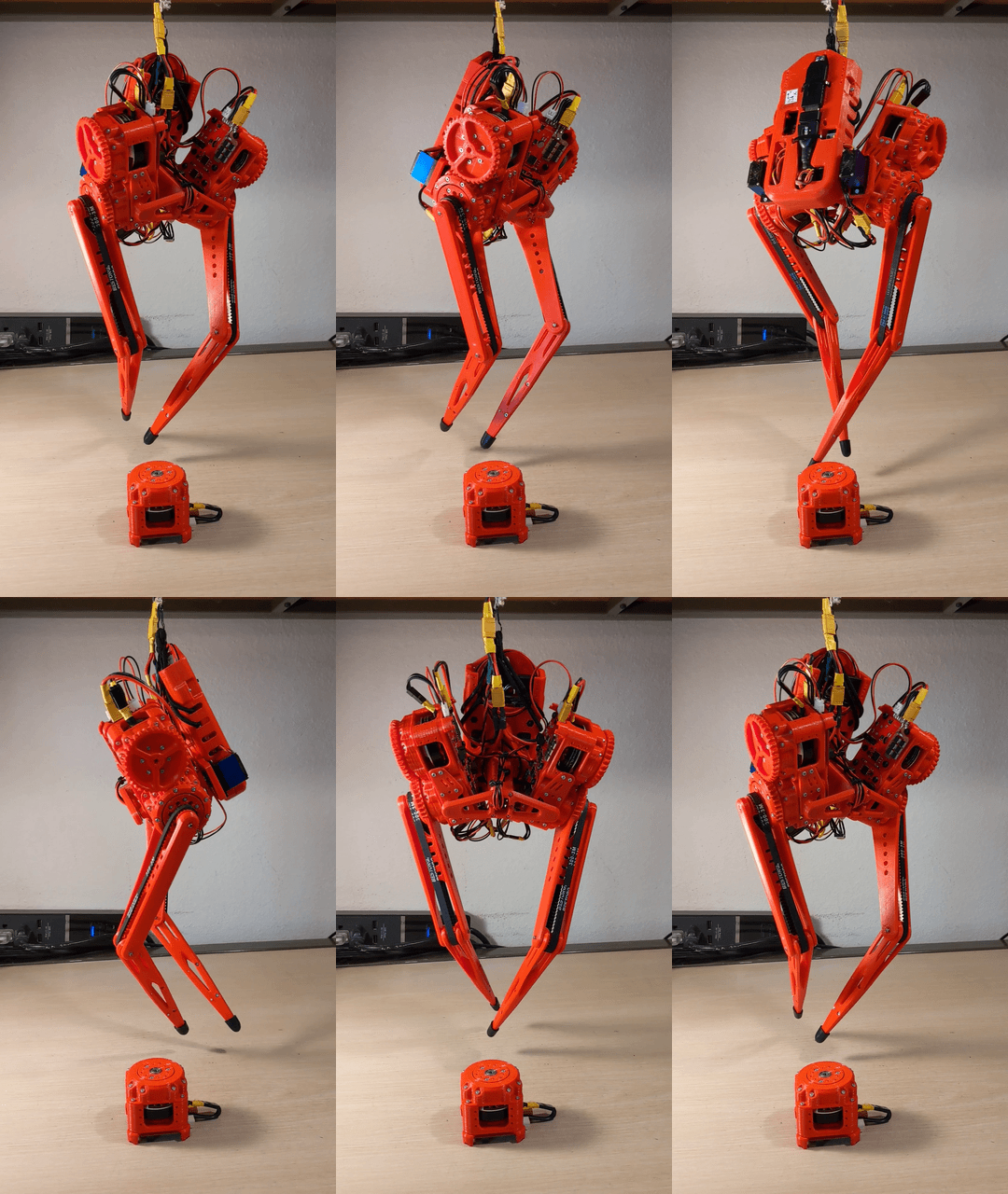
This is what the robot looks like now!

In the last couple months I had to redesign TipTap's beaglebone blue backpack, due to the integrated RS485 to uart converter chips continuously burning out, and in general being unreliable. I tried several other converter chips but had trouble finding another reliable and cheap option. In the end I had to move to a larger form factor by integrating a "JBtek USB to RS485 Converter Adapter ch340T" (the large black usb stick now on the back of the robot), which works very reliably, and as an additional plus lets me plug in the converter to any computer to test the motors very easily since it's just a usb stick.
After that resign, I ran into software and networking difficulties using the beaglebone's integrated solutions. Eventually I moved to a setup where I SSH into the board via VSCode over wifi, which works like a charm and has really sped up my software development workflow.
The power mangament also let to some difficulties, the servo rail is only connected to the lipo battery input terminal on the beaglebone, so I needed to "fake" a lipo input instead of being able to use the standard power connector on the beaglebone. To do this I take the 24v power supply and pass it through a buck converter down to 8v which powers the servo rail and beaglebone, unfortunately, the lipo terminal has a battery management circuit integrated into it which will interpret the slow ramp-on of the buck converter as a bad battery and prevent further current draw (preventing the beaglebone from turning on). As a workaround I'm plugging the power in, waiting for the buck converter to stabilize, and then plugging in the buck converter into the beaglebone. I'll do this until I can come up with a compact power-on-delay circuit that does this automatically (as long as it doesn't impact my < $500 robot goal).
Most recently I've been dealing with a latency issue with reading the IMU's DMP fused quaternion data. So, for the moment I've resorted to using just the accelerometer data, which has negligible latency. Which finally let me test out some simple control routines while tethered.
The code that created the behavior in the above video isn't very complicated, it's just a PID loop position to torque controller tuned to make the legs really springy and compliant. I'm using weighted averaging as a low pass filter on the accelerometer data, and fed all that data in as simple heristic proportional gains, all manually tuned at the moment (I'm just using this to test the hardware / compute performance, later on I'll move to more advanced control schemes). Here's the python script:
from tiptap import *

CustomCal = [-223.67956054016938, -493.2387273975738, 93.62142366674297, 778.4646372167543]
Controller = PIDloop(InCalibration=CustomCal,TorqueLimit=0.4)

avg_zaccel = 0.
avg_xaccel = 0.
avgz_ratio = 0.4
avgz_inv_ratio = 1 - avgz_ratio
avgx_ratio = 0.8
avgx_inv_ratio = 1 - avgx_ratio
while True:
    accl = mpu9250.read_accel_data()
    avg_zaccel = avg_zaccel*avgz_ratio + accl[2]*avgz_inv_ratio
    avg_xaccel = avg_xaccel*avgx_ratio + accl[0]*avgx_inv_ratio
    Roll = -avg_xaccel*7
    Rtheta1,Rtheta2,Ltheta1,Ltheta2 = gla.GetLegAngles(-avg_zaccel*0.15 + 3*np.pi/180 + np.pi/2, np.mod(int(time.time()/0.3),2)*2-1)
    RightLegServoDeg(-2 + (Roll>0)*Roll)
    LeftLegServoDeg(-2 - (Roll<0)*Roll)
    Controller.Apply([Rtheta1*180/np.pi, (-Rtheta1-Rtheta2)*180/np.pi, -Ltheta1*180/np.pi, (Ltheta1+Ltheta2)*180/np.pi])

ExitProgram() # shuts down motors and cleans up signal handlers
 Darren V Levine
Discussions
Become a Hackaday.io Member
Create an account to leave a comment. Already have an account? Log In.