 Görkem
-
1Prototyping
Note:
I didn't use sketches/drawings for the brass structure, after 3 days of trial&error I ended up with this. So in these instructions I'll provide you the wiring schematics, explain the code and tell you how I managed to solder the structure. But I can't provide dimensions, etc. since I also don't know them.
Parts:
- All the parts in the components tab
- lots of jumper cables
- A breadboard
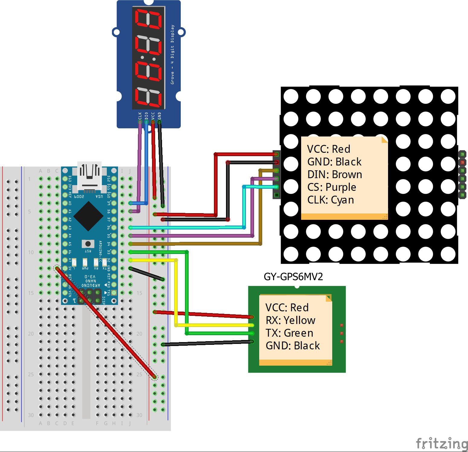
Here is the wiring schematic:
![]()
I always prototype first to develop the code and test it before making anything permanent.
![]()
After you're done with wiring upload the code "Astroclock.ino" provided in the files tab to Arduino and wait a bit. The GPS should lock into a satelite soon enough and you'll see the matrix and display light up.
-
2The Algorithms
The code Astroclock.ino is commented so you'll have an idea of how the code works upon examining it. Here I will tell you which algorithms I used and implemented in the code.
John Conway's Moon Age Algorithm
John Conway is an English mathematician who came up with the method of mentally computing the day of the week for any given date. Also a method to calculate the age of the moon for any given date. The error rate for this method is a liitle larger than other longer methods but in my case it works well because I only display the 8 phases of the Moon.
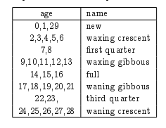
I implemented the algorithm to arduino as a function called conwayMoon(year,month,day) which takes the year,month and day from the GPS as input, and returns the moon age as output. Than I used this output to draw the Moon phase on to the matrix display using this table:
![]()
Calculating Local Sidereal Time (LST)
The formula to calculate LST is:
LST = 100.46 + 0.985647 * d + long + 15*UT
where,
d = the days from J2000 (more info here)
long = longtitude from GPS
UT = Universal time from GPS converted to decimal hours
This formula gives the LST in degrees. Then it is converted in the format HH:MM.
-
3The Structure
Tools & Parts:
- 0.8mm and 1.00mm Brass Rod or Wire
- Soldering equipment
- Pliers
- Diagonal cutting pliers
I didn't have acces to brass rods since they are not avaliable in my region. Thus I had to use brass loop wire and straighten it.
The first structure I tried was a mess and unstable because I used a larger square for the base and the bent points were visible seen here:
![]()
Later tried a smaller base which I was happy with:
![]()
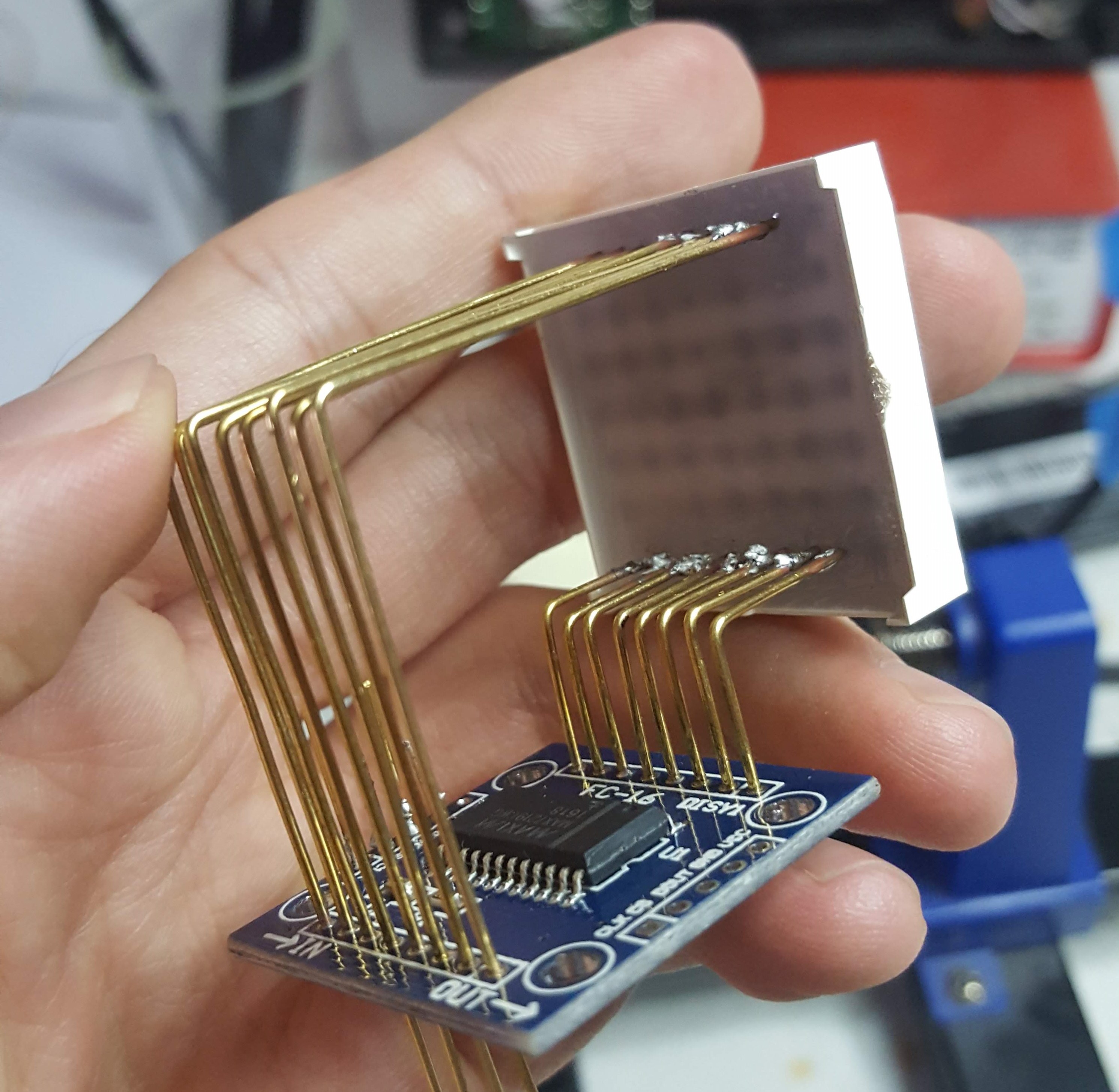
Instead of soldering the 8x8 matrix to the driver directly, I soldered them using brass wires which gave this cool look:
![]()
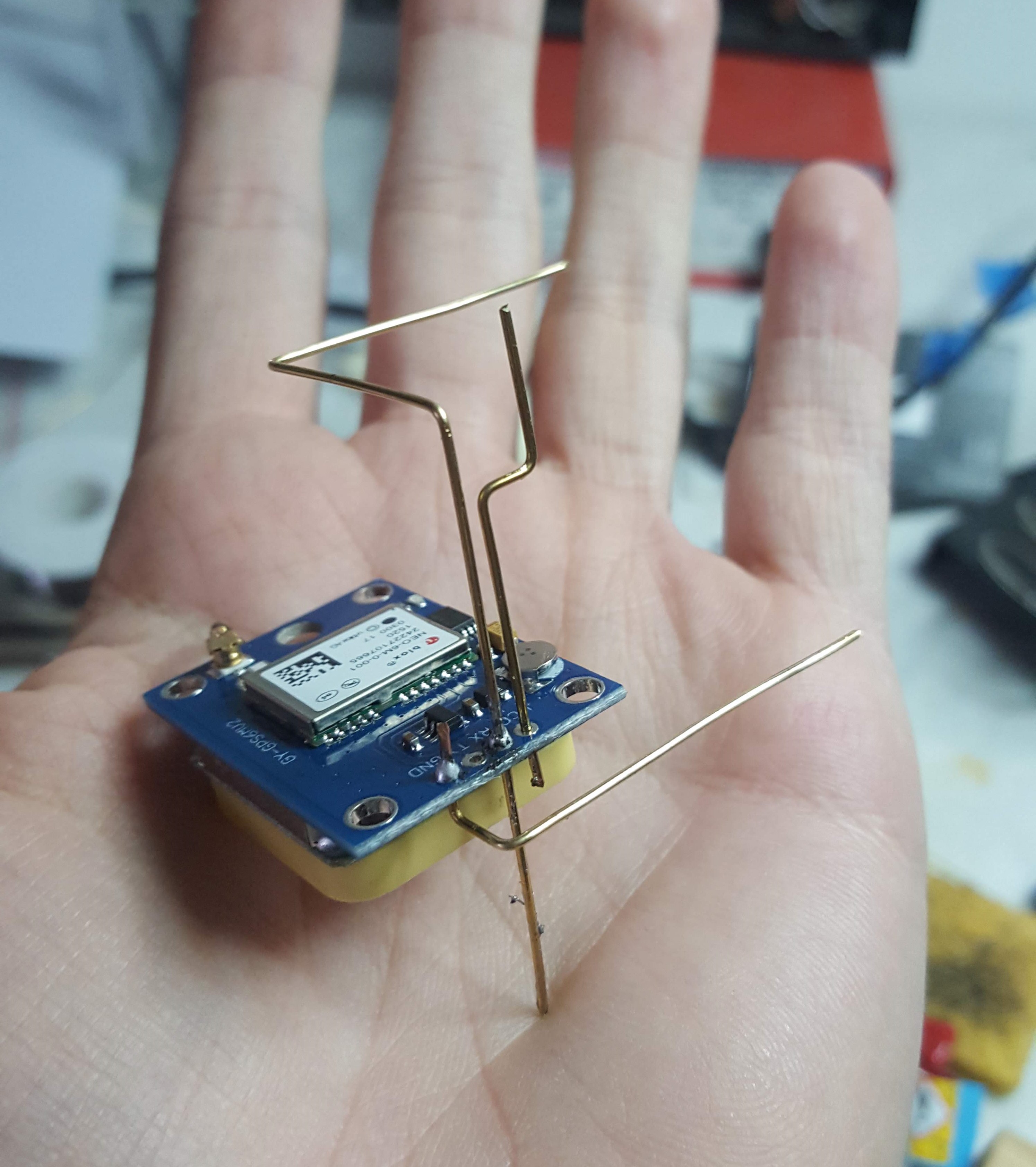
I bent the wires estimating the dimensions by eye:
![]()
In every step I tested if the components worked correcly.
So what do you think? All kinds of feedback is welcome!
Freeform Astronomical Clock
Arduino powered Astronomical Clock in freeform, which displays the lunar phase and Local Sidereal Time(LST)


Discussions
Become a Hackaday.io Member
Create an account to leave a comment. Already have an account? Log In.