Close
0%
0%

Digital Transistor Matcher/Tester

An automated transistor tester, as well as matched pair finder, for DIY synthesizer projects.

Similar projects worth following
709 views
Analog synthesizer circuits will often call for "matched pairs" of transistors. The critical parameter for this matching is the base-to-emitter voltage of the transistors, which must often be matched to within ±5mV. This matching is often done with a breadboarded circuit and voltmeter, or with a simple "pass/fail" pair tester. This project will use a microcontroller with a high-resolution analog-to-digital converter to allow the user to not only find matched pairs more easily, but also to keep track of the readings from each transistor tested, in order to allow the parts to be "binned" (separated into groups of devices with similar characteristics). Additionally, this project will include sockets not just for the common TO-92 three-lead package, but also for parts in SMT packages such as SOT23 or SOIC.

Credit where credit is due: 

This project is based on the automatic "pass/fail" transistor matching circuit by the late and much lamented Ray Wilson

Which, in turn, was based on the transistor matching circuits developed by Bob Moog, who needs no introduction.

If it turns out that my only innovation in this project was "have a microcontroller do it," well, maybe that's enough.
  • Prototype power supply

    Kuri P. Yon01/05/2019 at 07:53 0 comments

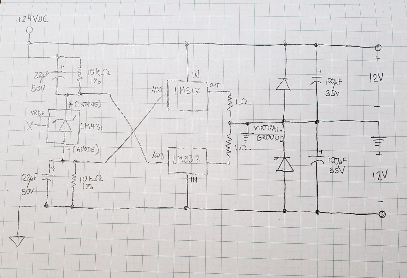
    For the prototyping of this project (and presumably many others), I had actually planned to use the benchtop DC supply that I had ordered, the Rigol DP832, but it isn't going to be delivered on time, and I really wanted to get going on this project. The usual solution for needing a bipolar power supply, two 9-volt batteries in series, wouldn't work here because I need at least 12V supply rails. So I put together a circuit that splits a +24VDC supply into ±12VDC supply rails, using a TL431 voltage reference and LM317/337 adjustable positive/negative linear voltage regulators:

    (Sorry for the ugly hand-drawn schematic, but I didn't feel like drawing it into a CAD program.)

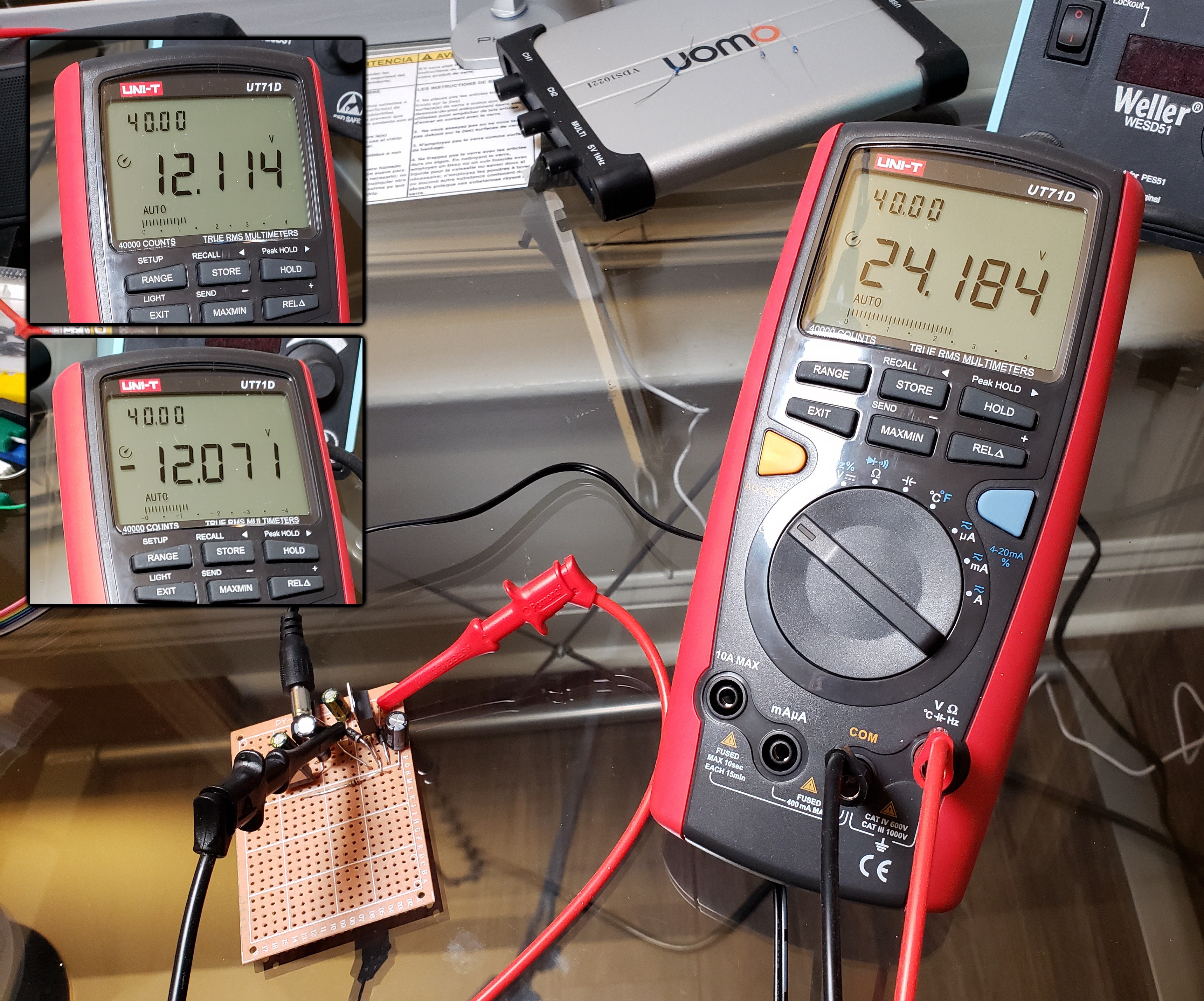
    Anyway, after a bit of messing around with things, I finally got it to where at least it looks stable on my meter:

    Not a perfect split, but it was never going to be. I'm going to check the supplies for noise before I go ahead with using it, but at least I now have a way of moving forward on this project.

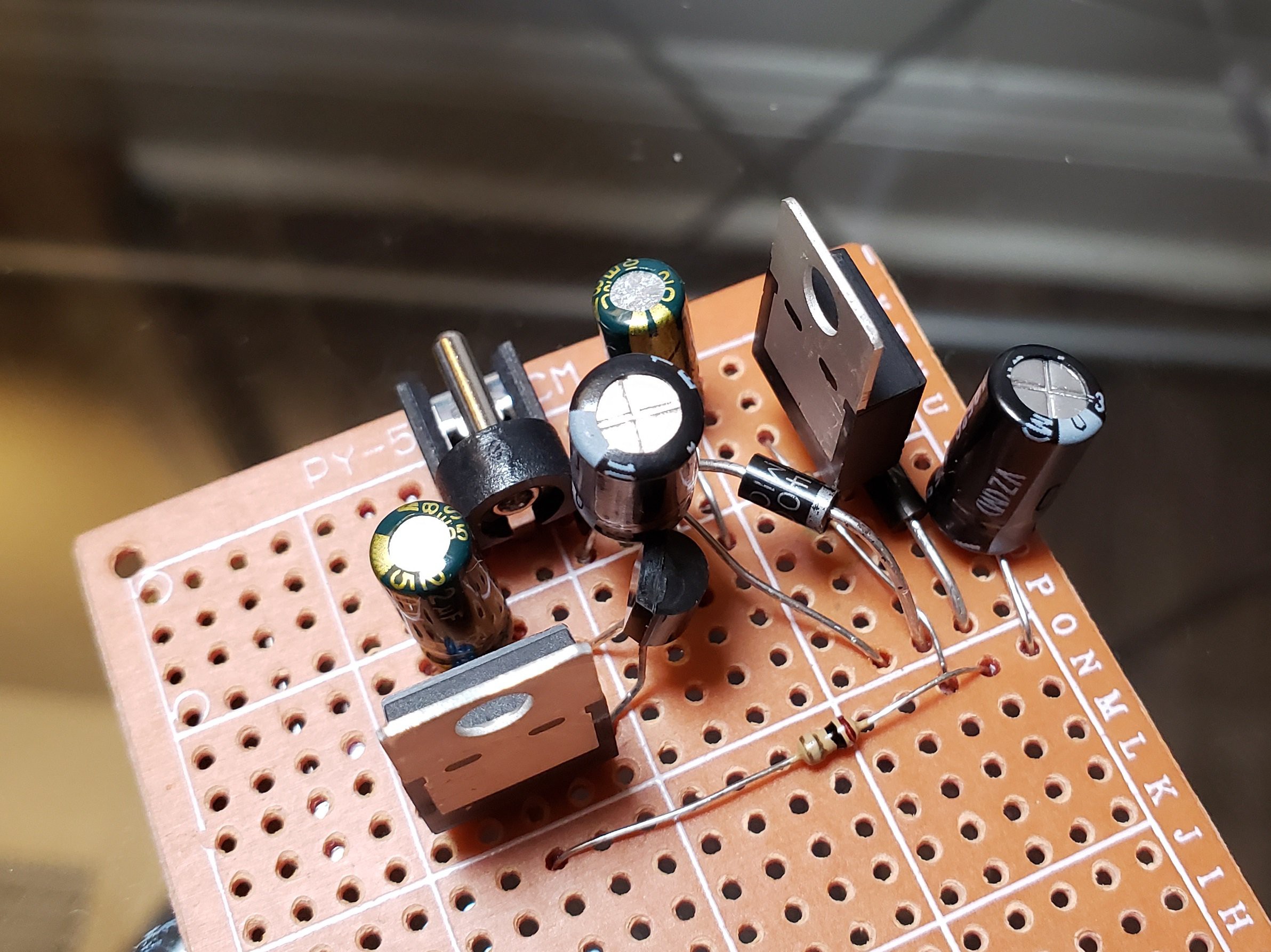
    Oh, and just for giggles, this is how the circuit ended up looking:

    It sure is ugly! And it sure does work! Function over form, people...

View project log

Enjoy this project?

Share

Discussions

Similar Projects

Does this project spark your interest?

Become a member to follow this project and never miss any updates