 MaBe42
-
1Central structure
I bent two hexagons out of 1mm wire and used three 1N4148 in three corners of the hexagon to have the two hexagons at a defined distance from one another. I saw this trick in one of the other contest submissions (Hypno Butt).
-
2LEDs
First I prepared the transparent white LEDs by griding off a bit of the tip and by slightly rougheing the outside of the remaining housing to improve the emission to all directions. Then I soldered them to the two hexagons. One of the hexagons connects all the anodes. The other one connects all the cathodes and is also common ground. I soldered three LEDs to each corner. A central one with long wires and two with shortened wires.
-
3The circuit
Although there is at least one other breathing 555 circuit in the contest (555 timer LED heart beat) I looked for a simpler solution with only a single 555. I found one on solderpad.com. I used the circuit described there but modified the values of C to 33uF and R to 27k. Mostly because I had them lying around. For the LEDs I used a 100R as common anode resistor. I should have taken a lower one to make it a bit brighter. Maybe 10R would be nice.
-
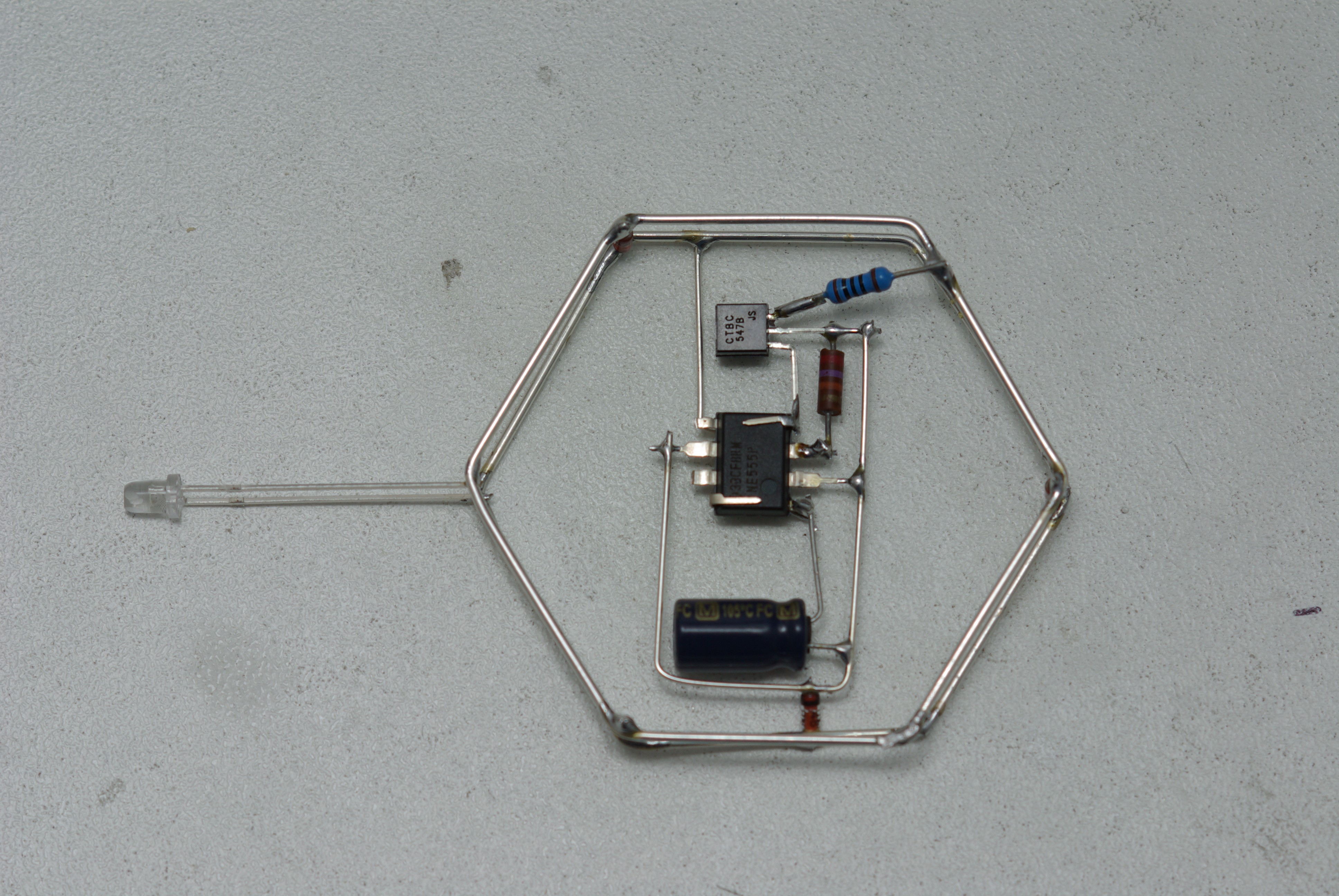
4The circuit as a sculpture
Since I wanted to use a binder clip for the battery holder I came up with a design where the circuit is between the cells. I bent the legs of the 555 such that all connected to plus are above the chip and the ones connect to ground are below the chip. All other pins i straightened and the unused I clipped off (pins 5 and 7). ! used an additional 1N4148 to mechanically stabilize the circuit inside the hexagon.
View from above:
![]()
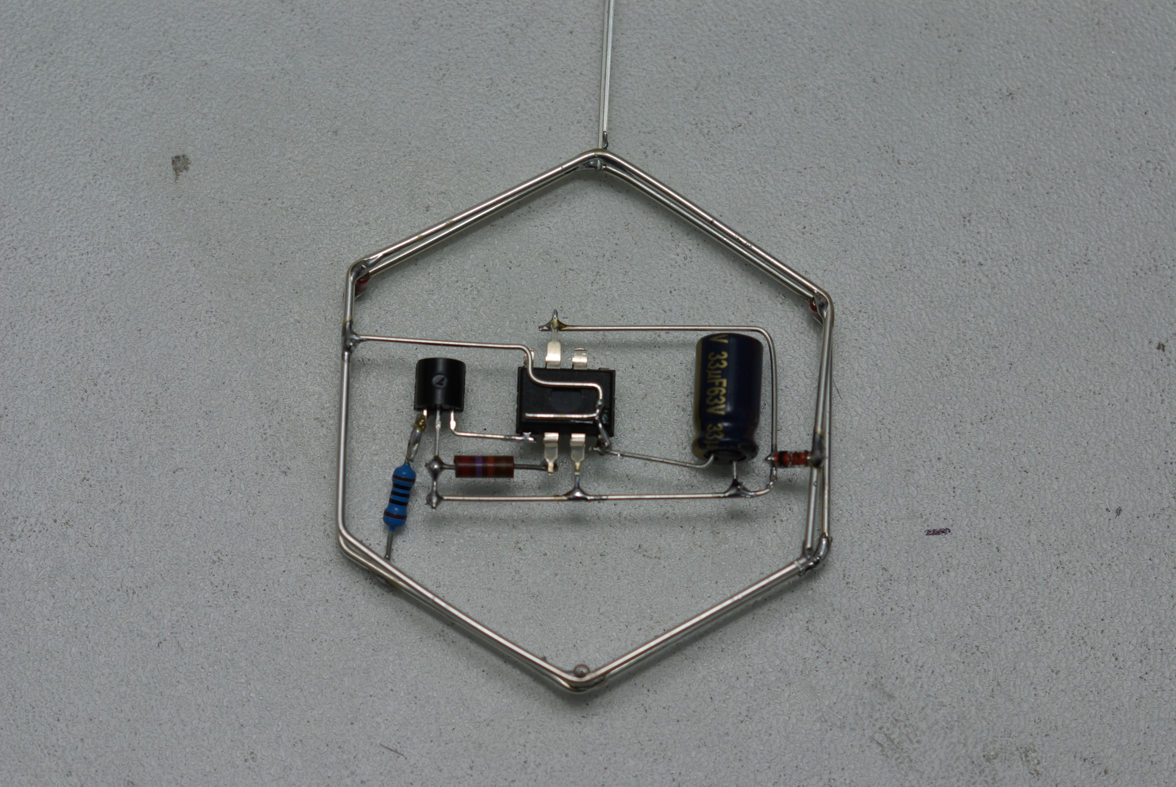
View from below:
![]()
Later I found out that this was not mechanically stable enough and added more stable contacts (see in the gallery).
-
5The coin cell holder
I had various sizes of binder clips lying around. So I chose one which was just large enough to hold two coin cells - I chose CR2025 because they are slightly thinner than CR2032 - and the 555 chip. The original binder clip was too big. Thus I cut it in half using my dremel with a grinding disc. Additionally I ground off parts of the paint inside the binder clip to make it conductive. Finally I had to to bend the handles that I could use them for the modyfied clip (see image in the gallery).
-
6Put it together
Well, the most difficult step. I don't know exactly how I managed. I sometimes had the impression that I needed three hands with tiny fingers. ;-) Unfortunately, I have no idea how to add any kind of on-off-switch to it.
555 breathing LED snowflake
Another circuit sculpture based on the 555 using a modified binder clip as coin cell holder
Discussions
Become a Hackaday.io Member
Create an account to leave a comment. Already have an account? Log In.