0%
0%
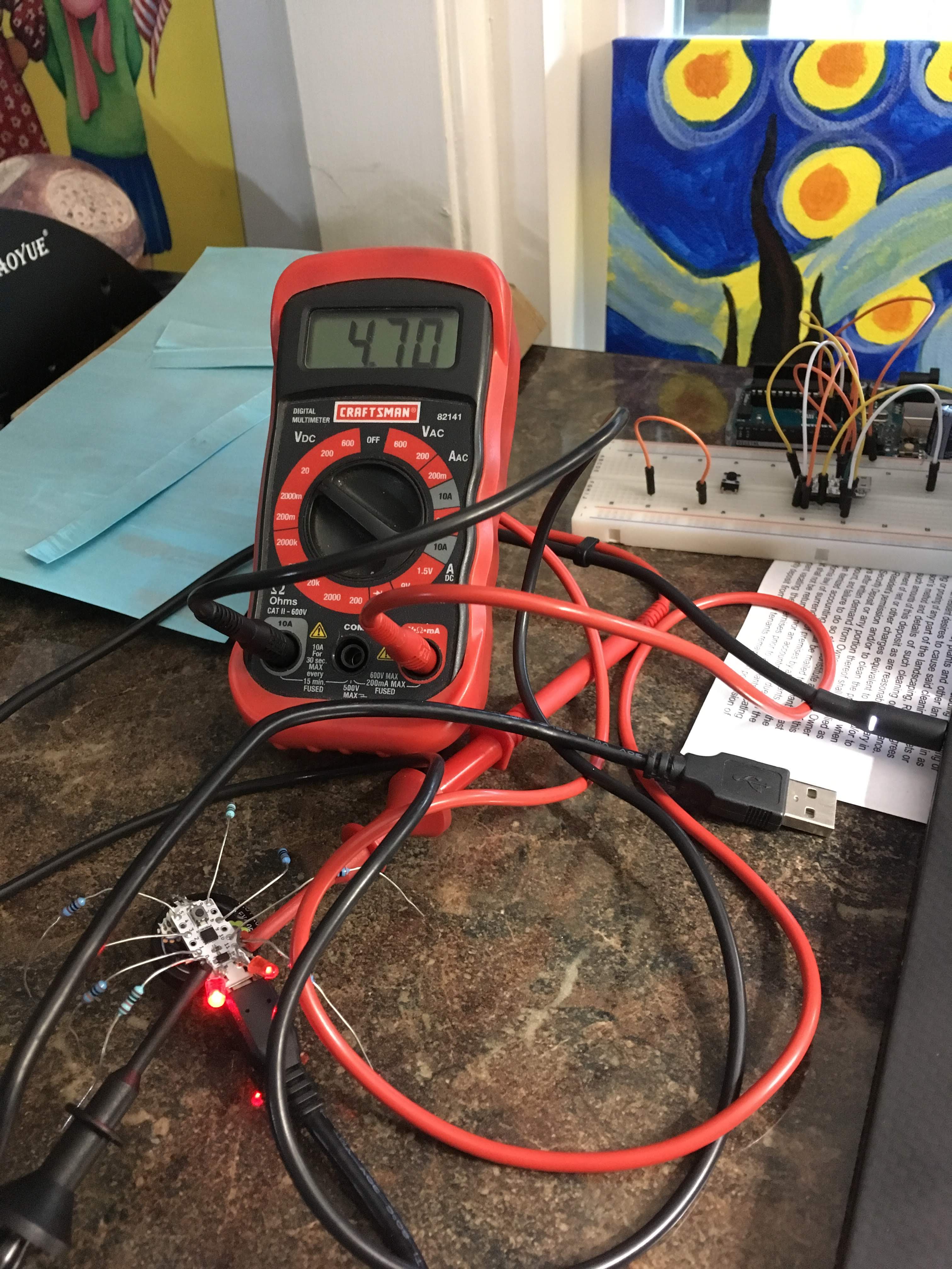
ATtiny Super Capacitor Spider
Little spider with glowing eyes powered by a super capacitor, and controlled by an ATtiny84a
 Sander van de Bor
Become a Hackaday.io member
Already have an account? Log in.
Just one more thing
To make the experience fit your profile, pick a username and tell us what interests you.
Pick an awesome username
hackaday.io/
Your profile's URL: hackaday.io/username. Max 25 alphanumeric characters.
Pick a few interests
Projects that share your interests
People that share your interests


 Ted Yapo
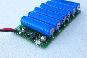
 Patrick Van Oosterwijck
 jaromir.sukuba
 Simon Merrett
This is nice project for me. I thought it would move but just the LED flashed.
That's first step. See the sketch like Arduino code. I try It, many many compiling error.
Is it that sketch compiling in Arduino IDE? My environment is Arduino 1.8.19. and installed
Spence konde's megaTinyCore.