 Michael Aichlmayr
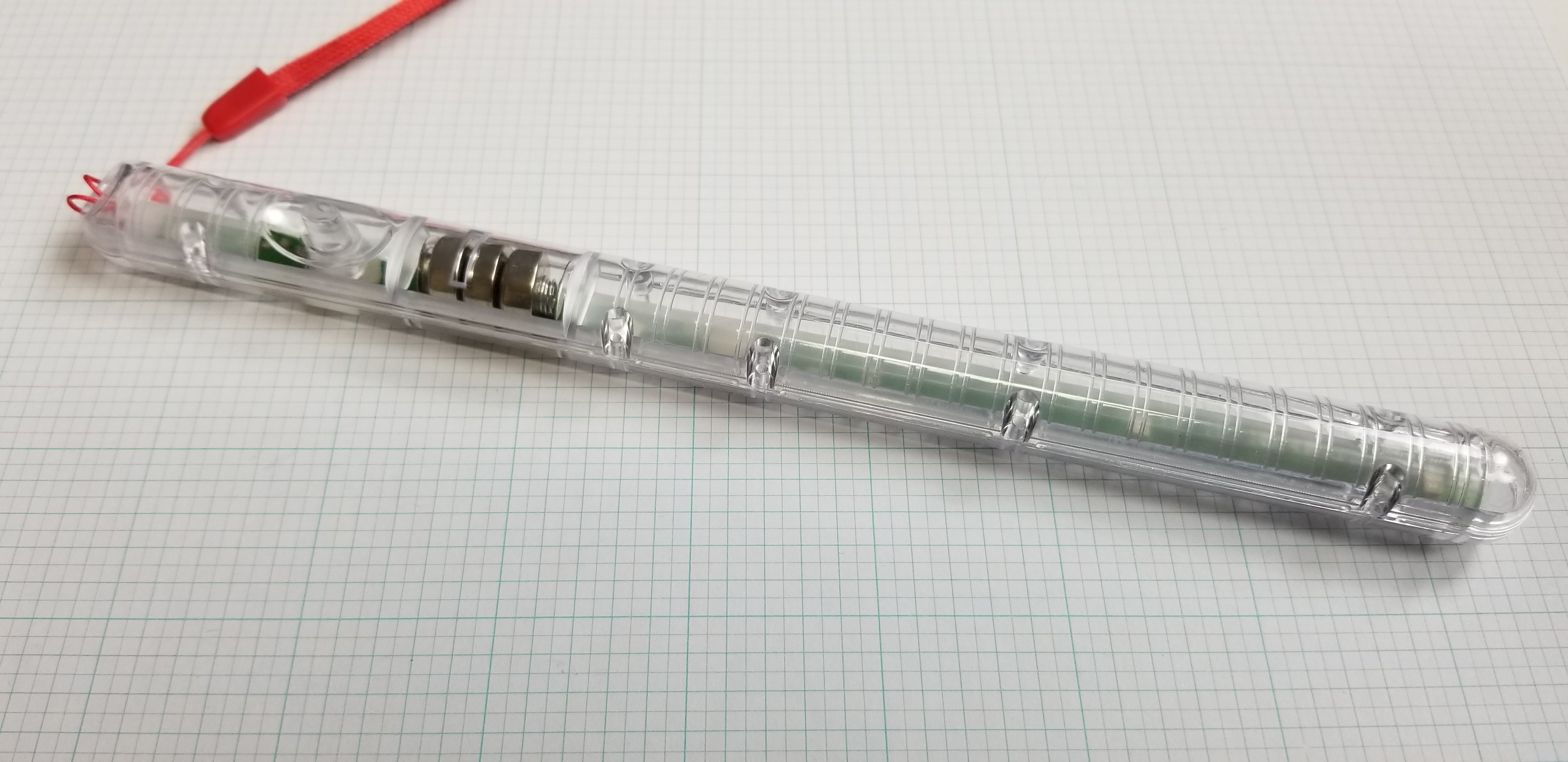
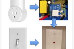
The flasher circuit was harvested from a toy. These flashing wands are glued together, and the batteries are "not replaceable". The only way to get inside one is to break it open. I've never successfully opened one without ruining the clear plastic housing, but I save the circuit boards hoping to reuse them someday.
Once the circuit board was liberated from the toy, the connections were mapped and it was cut down to remove the switch traces, and the original LEDs which I didn't like for this project (though I did desolder and save them).
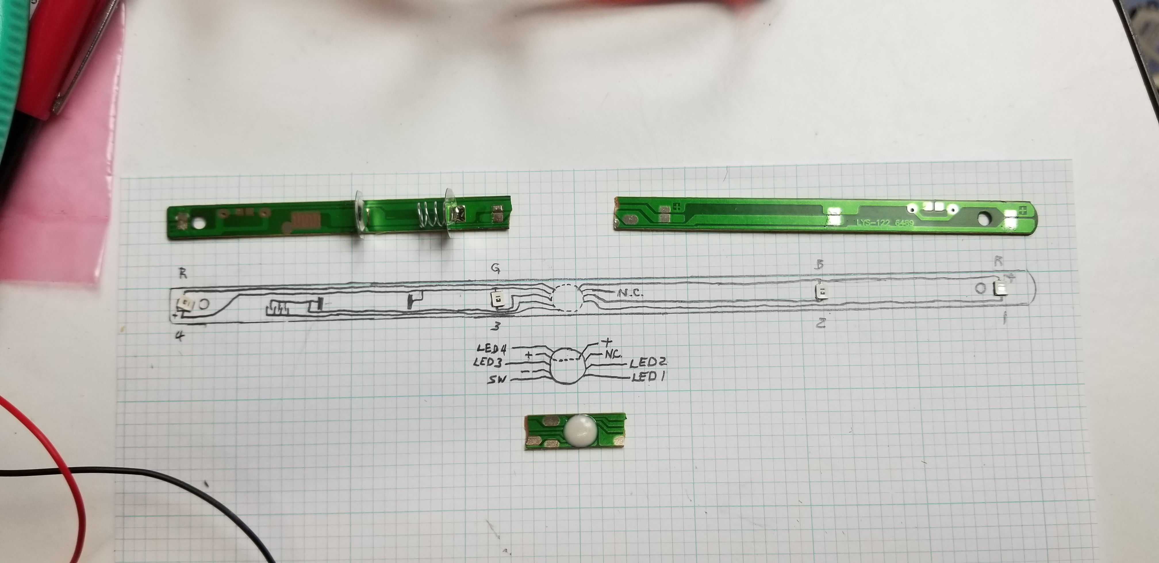
Once it was cut down, it was trimmed and the mask was cleaned off to expose the traces for soldering (later the rest of the mask was also removed for appearances).

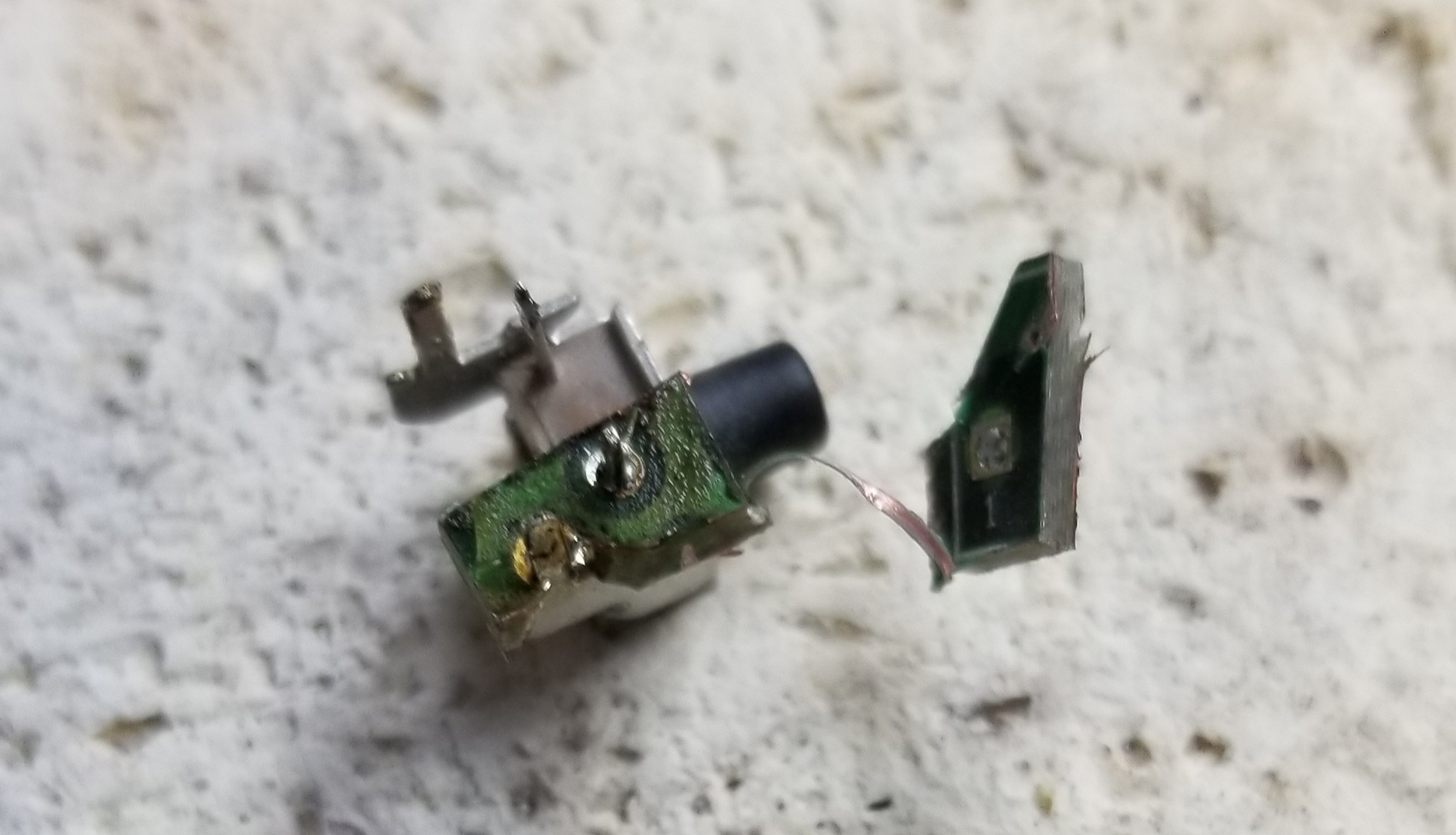
The switch came from an old circuit board. It was a beast to get loose without damaging it!

Thanks to my Dremel, I was able to cut around it, and section the remaining circuit board so it was easier to desolder.
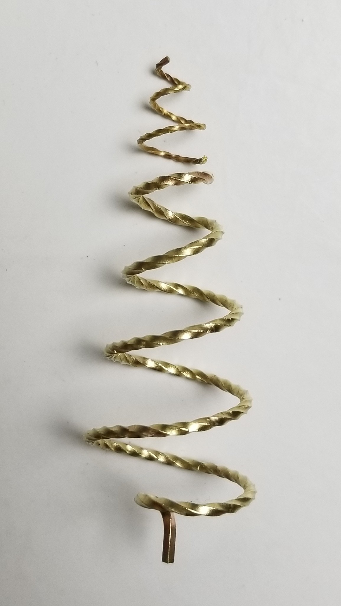
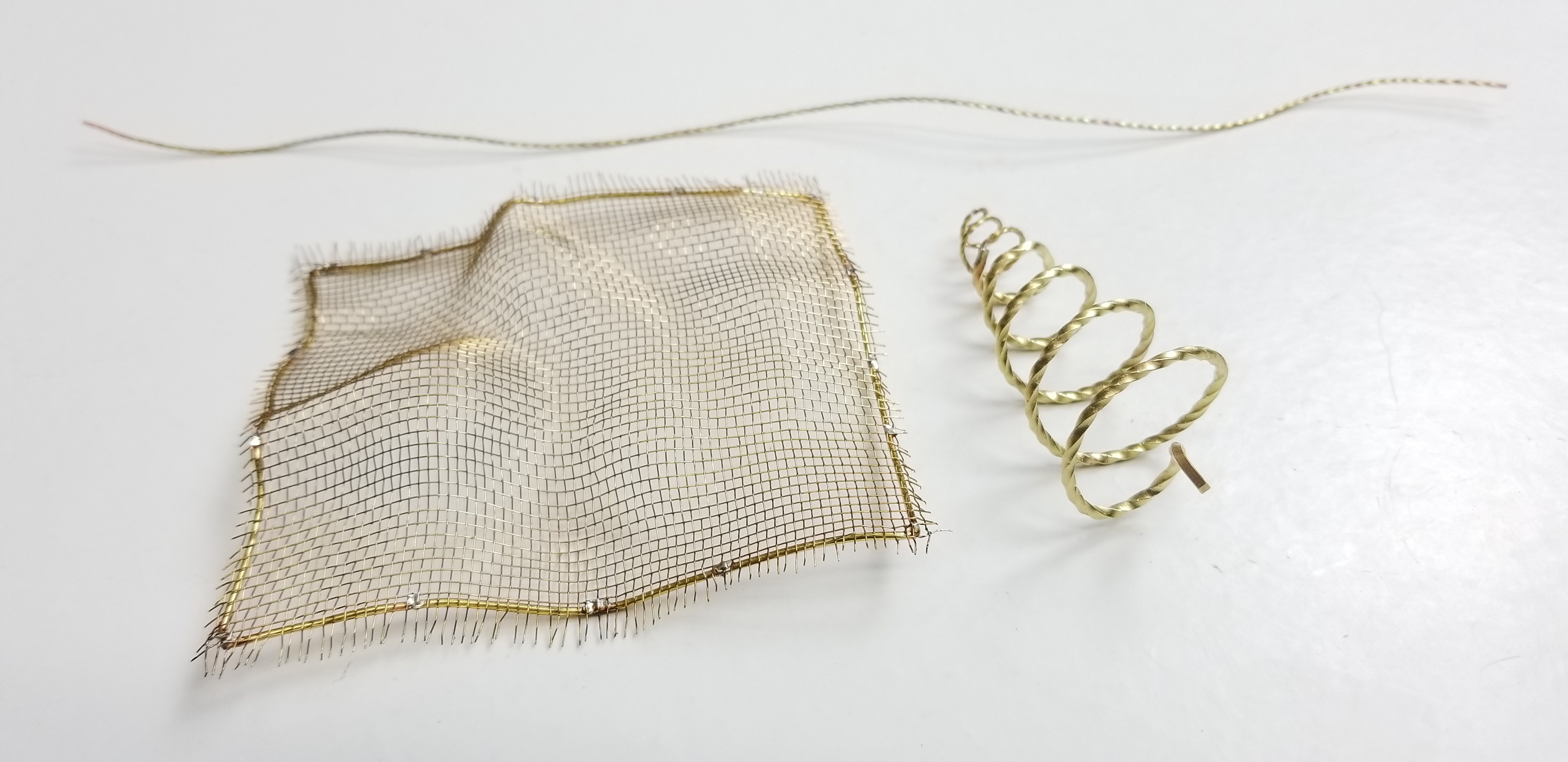
The spiral twisted wire was twisted by hand from square brass stock.
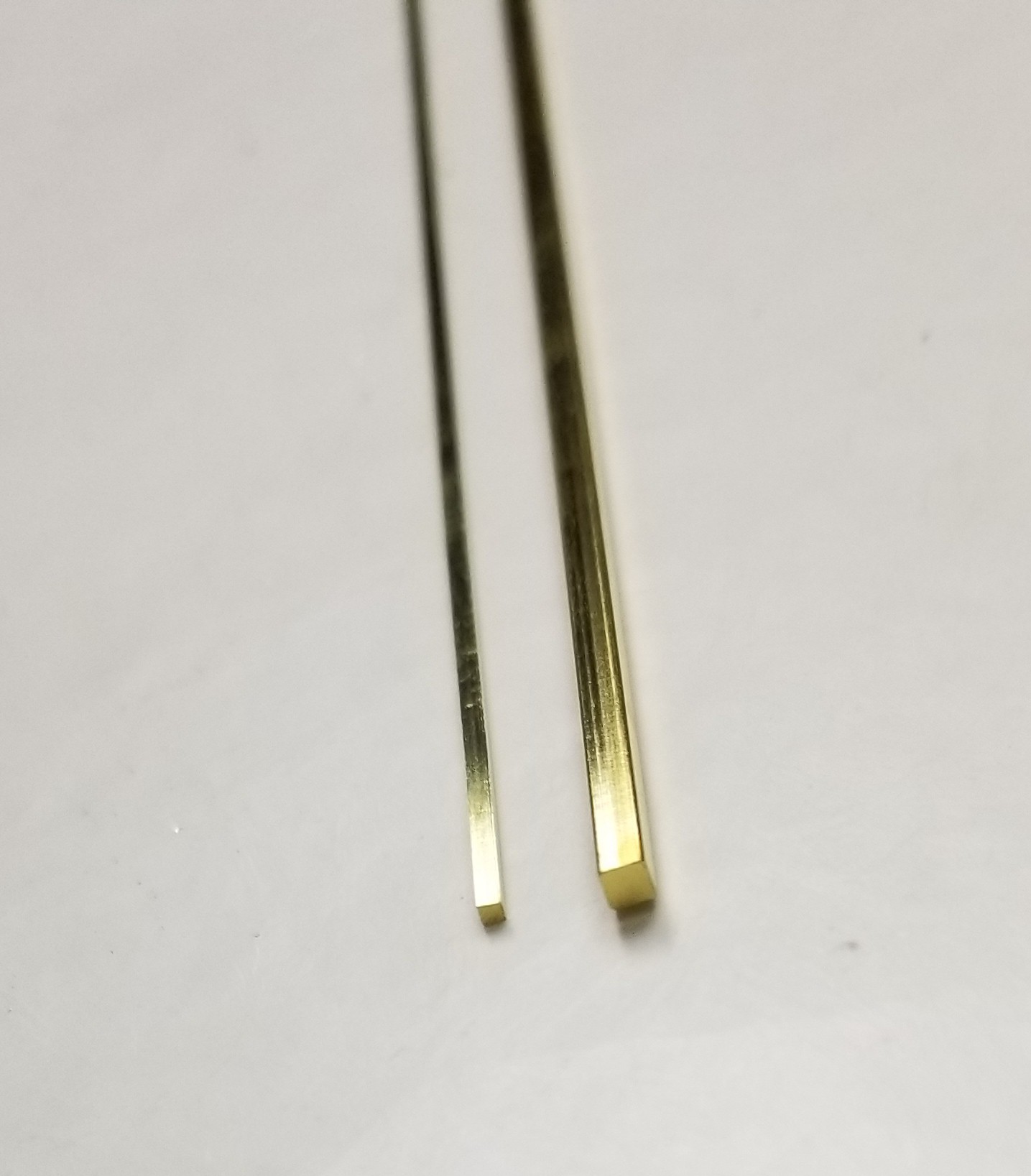
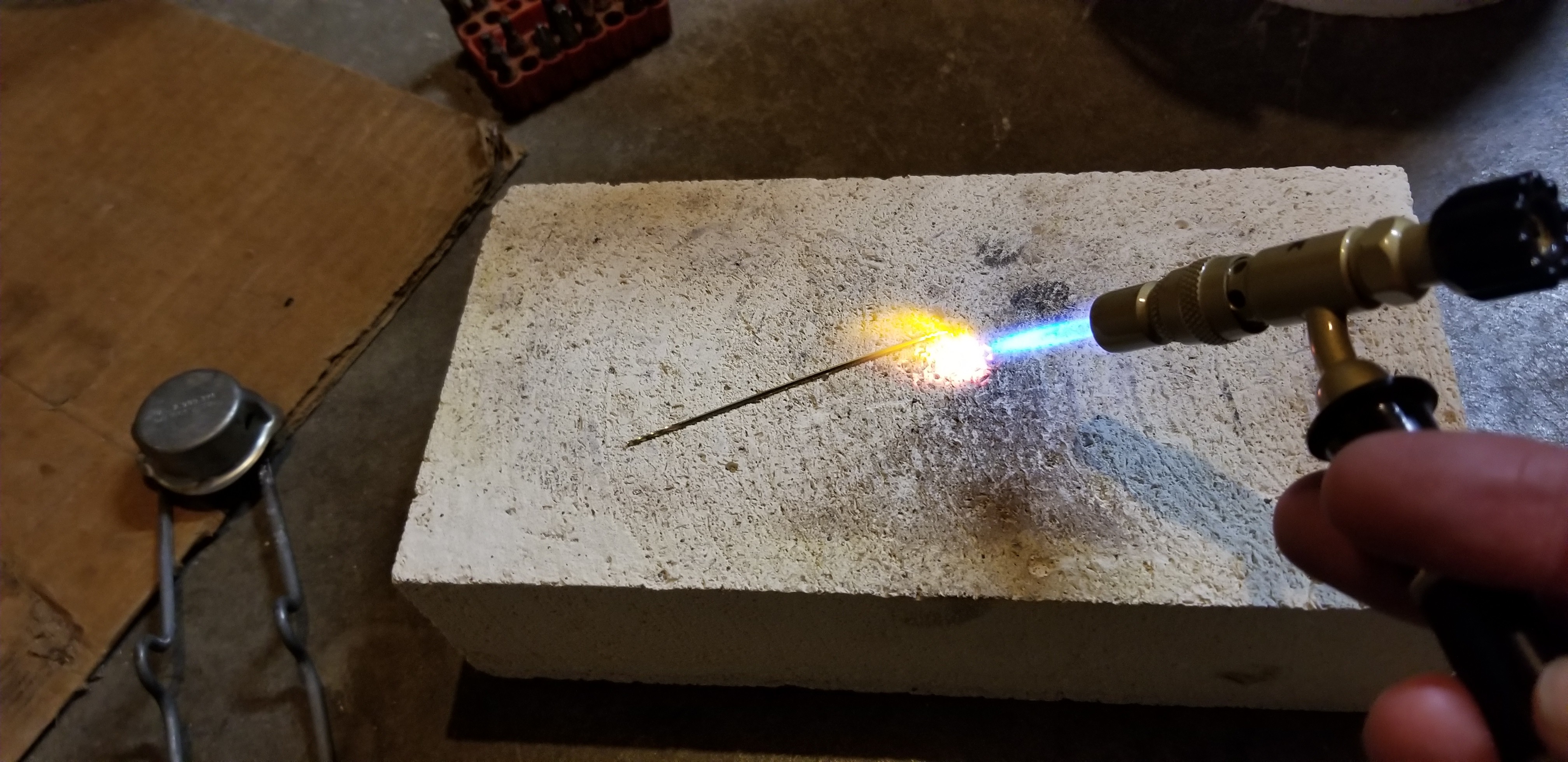
This wire comes "half hard". In order to twist it without breaking it due to metal fatigue, I had to anneal it to "dead soft". This consists of heating to a dull red, then quenching or allowing it to cool naturally. Quenching in a pickle pot helps to remove scale and tarnish, but I don't have one that could accommodate the long wire so I opted to let it cool and clean it later.
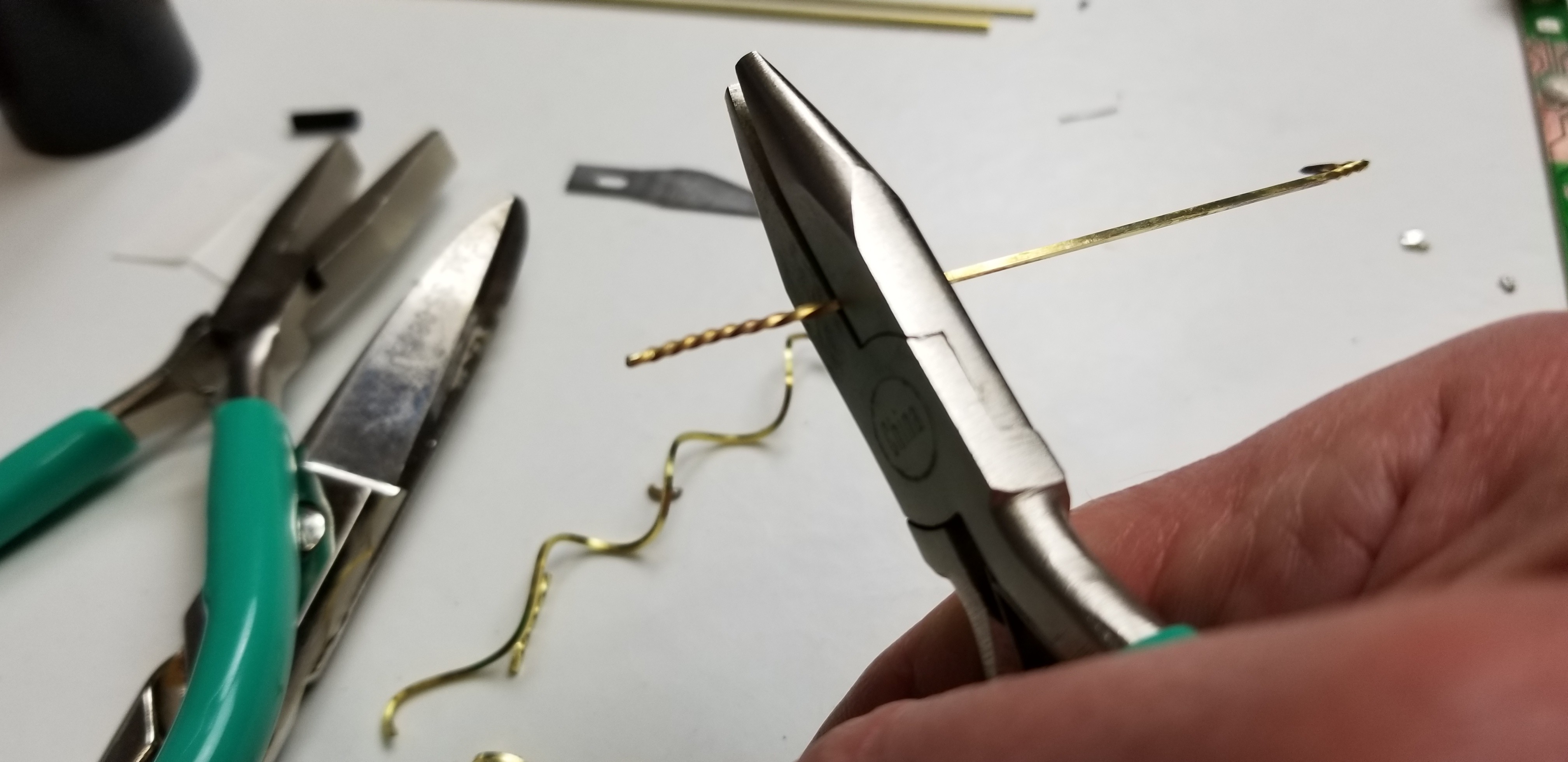
Once it was annealed, I twisted it using two pair of pliers. I held the wire with nylon lined pliers (not shown) to protect the twist and twisted the other end using flat noise pliers. Twisting the wire also work hardened the metal and returned it back to about "half hard", which is perfect for this kind of work.
Once twisted, I coiled the wire into a flat spiral, and then pulled it up from the middle into a tree. The tree was made in two parts.
Throughout this project I had to devise various jigs to hold my work while I soldered. Sometimes this can be very frustrating, but I usually find the right technique.

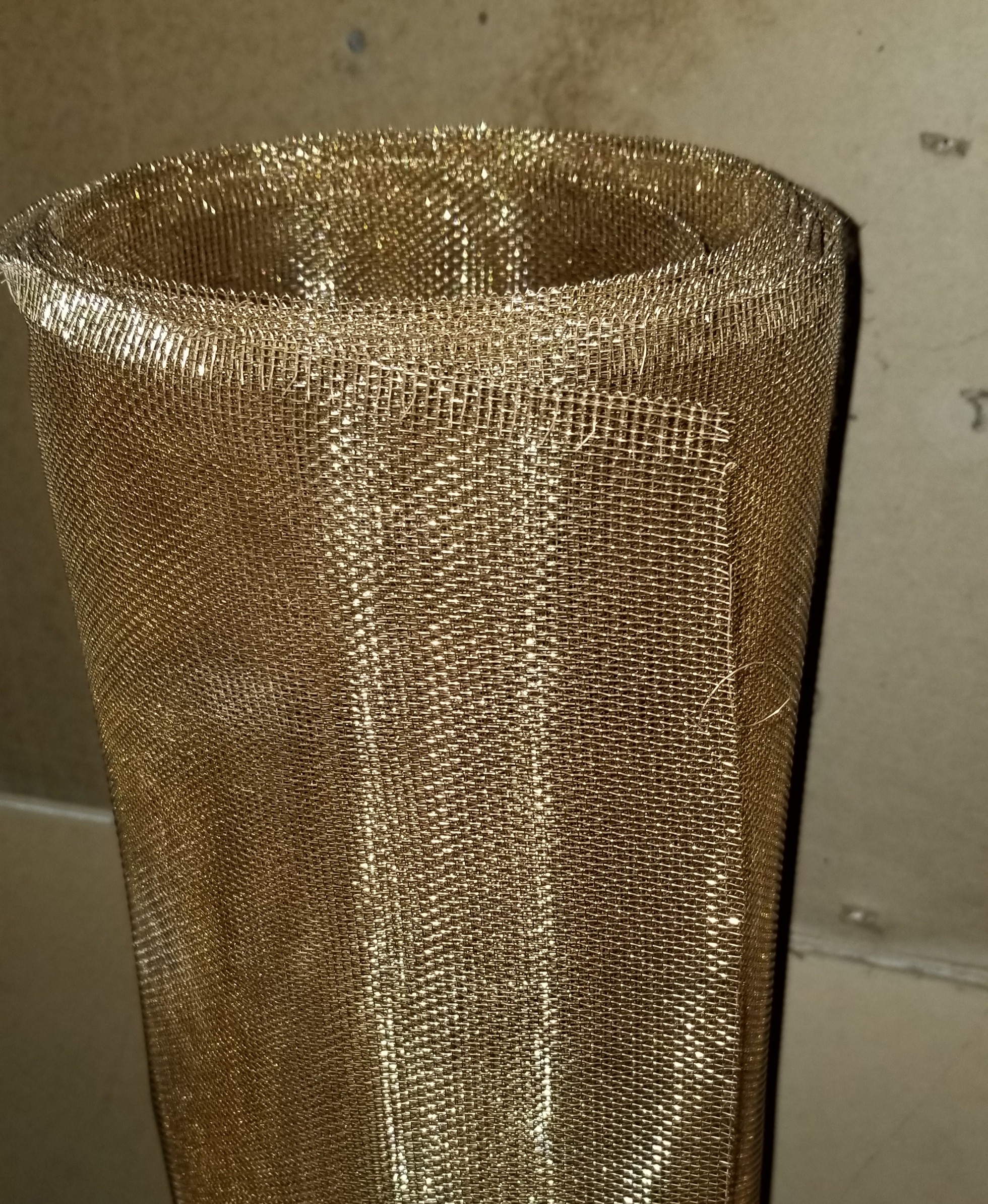
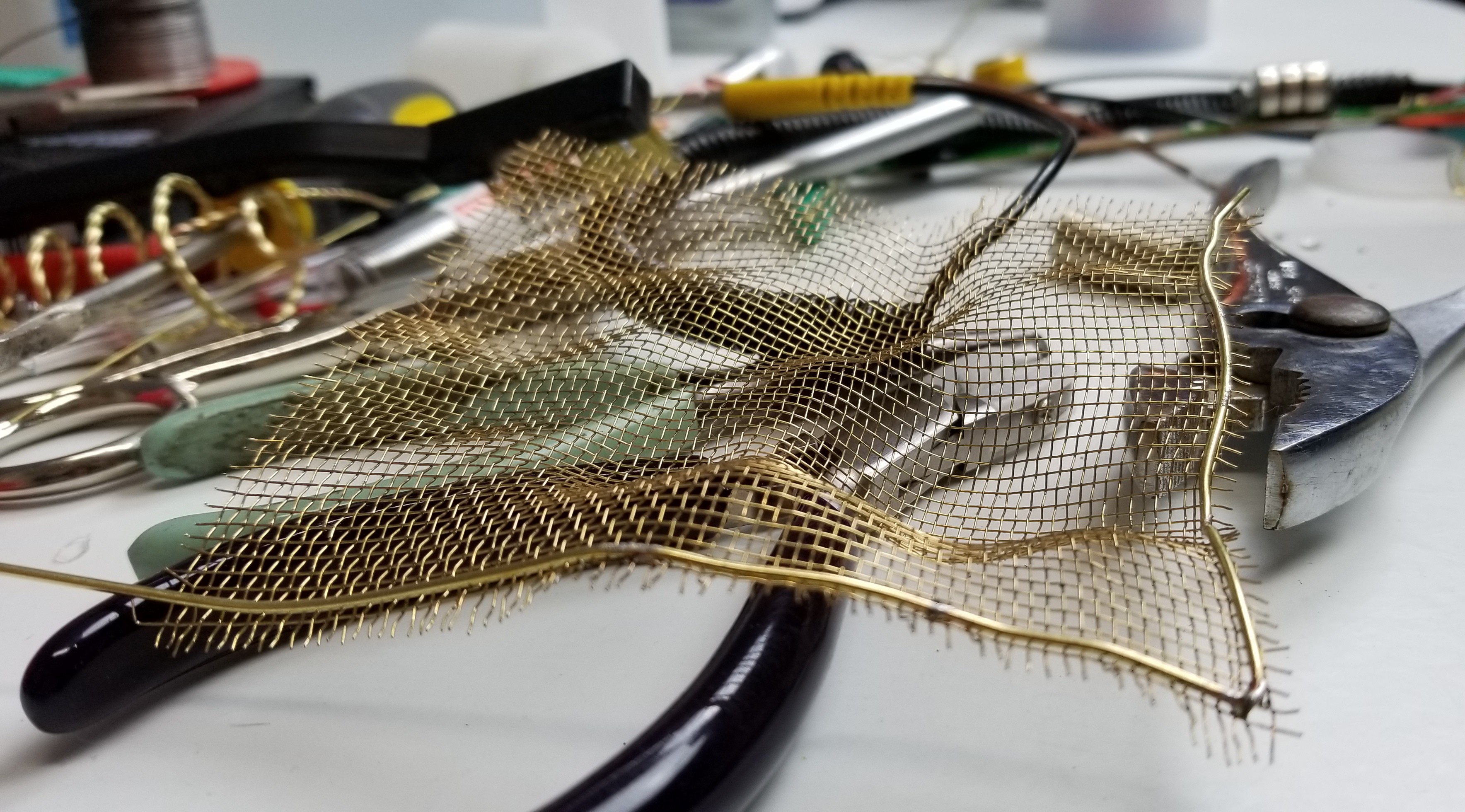
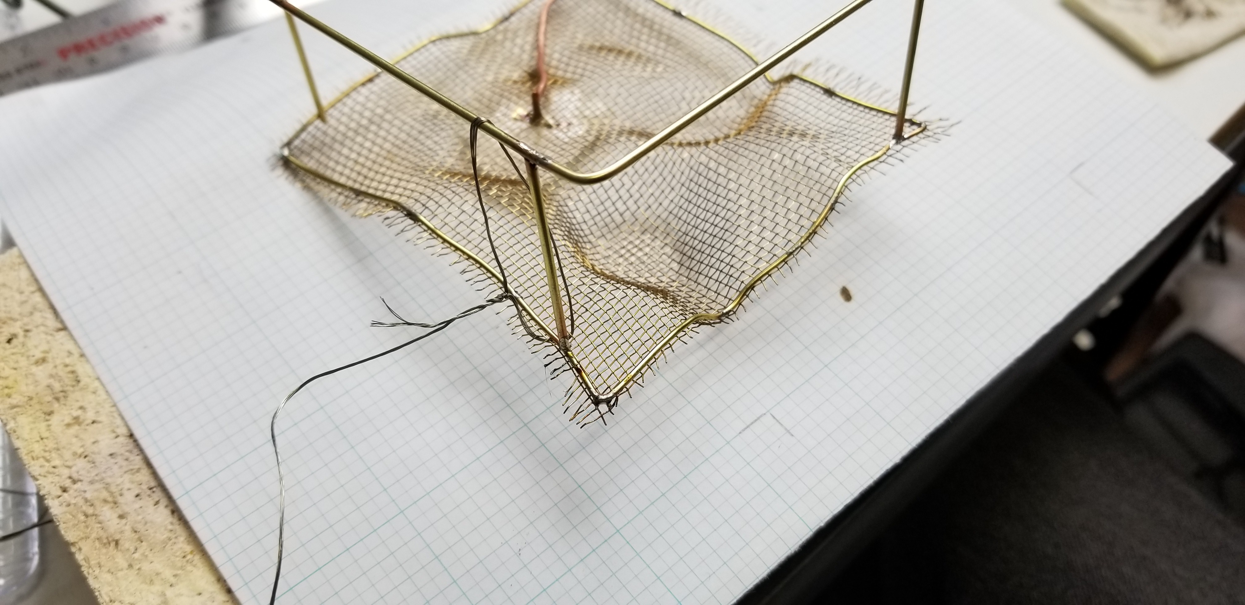
The "land" was made from brass screen I rescued from a Faraday shield that was used in a short term project to test phone apps with bad cell reception. I didn't really have plans beyond the tree and flasher circuit until I found the screen while looking for something else. The moment I saw it, the next step formed in my head. Serendipity!
I started by cutting an approximately 4"x4" square from the screen. I then deformed it with my fingers to create the rolling hills effect. Once it was deformed, I used 1/16" brass rod to create a frame for it. I bent the rod to fit the deformations, soldering the screen to it every inch or so.
These rods come 12" long, and didn't make it all the way around the screen. To continue, and close the frame I used a scarf-joint.
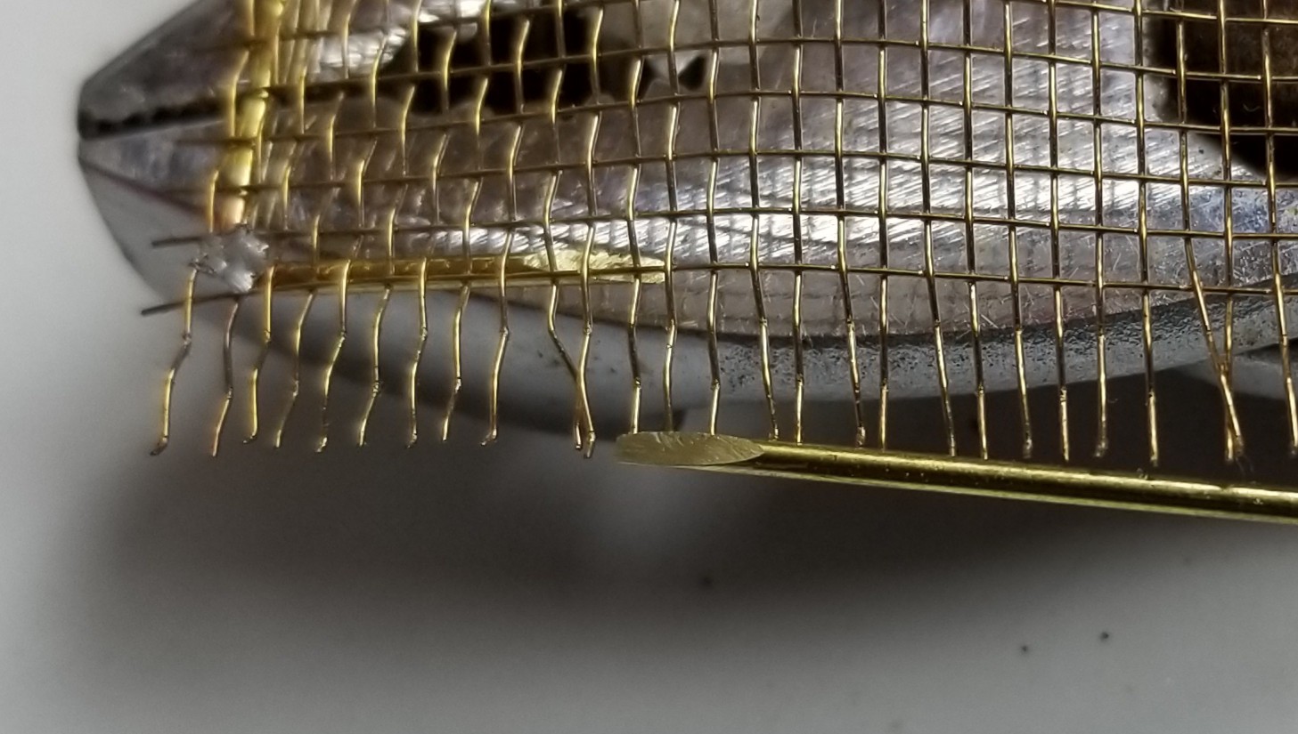
As solder joints, scarf-joints are stronger than butt-joints (perpendicular flat ends), but in hindsight, I think for any future projects, I will braze this kind of structural joint, and leave the solder for the electrical connections. Under stress the solder breaks, making bending after joining them difficult. I also had trouble protecting the joints from melting when I soldered something close to them. Alligator clips went a long way toward sinking the heat away from the joint, but this would have been easier if I didn't have to do it.
Once I had the twisted spiral tree, and the land finished, I realized the screen wasn't going to be strong enough to hold the tree on its own, and the idea of roots came to me. For that I would need some "underground" space for the roots.
I started, by making another frame. This one needed to be square, so I got out the cruel master, graph paper!
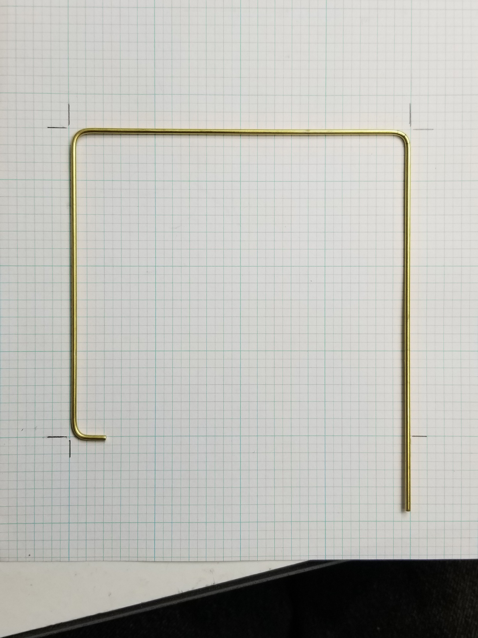
After some fun hitting the marks, and a couple more scarf-joints later, I had a frame.

After some jigging, and soldering, I had my underground world to fill in with copper roots to contrast with the brass of the "top-side" world.
After a few...
Read more »


 Eric Moyer
 Daniel Domínguez
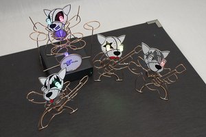
 Roger
Roger
 Adam Redfern
This LED flasher is looking very awesome I watched some similar products on ittermann you an visit here to see those.