 shane.snipe
My goals for this project are as follows:
$10 BOM cost, batteries not included.
No glue used in assembly
The parts should be made in 30 minutes or less
Parts should be easily shippable
Assembly should be manageable for a middle school student
Every piece should fit together with a sense that it belongs
Ideally I teach my daughter how to run a business from this project
Make it repeatable version of the very one off
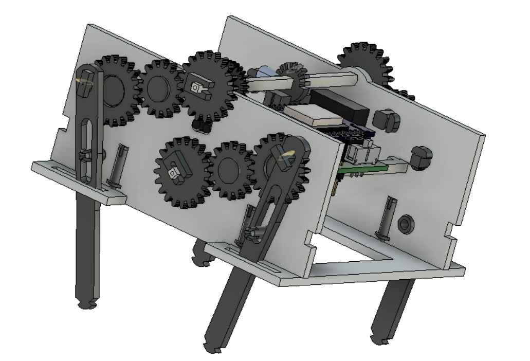
Tortellini the Turtle bot I made 8 years ago
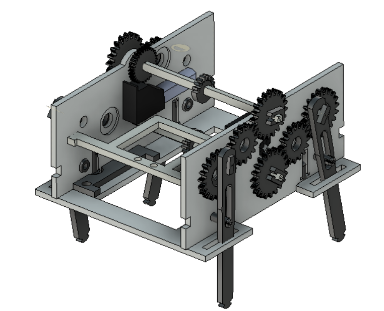
Now it is time to do at least as good I as I did with this bot in a reproducible way. The above bot was all glued together with 4 motors and 4 photo sensors. The MCU was 16F pic and it ran on an interrupt driven code but it was definitely a one off labor of love. There was zero design for manufacturing incorporated in the design.
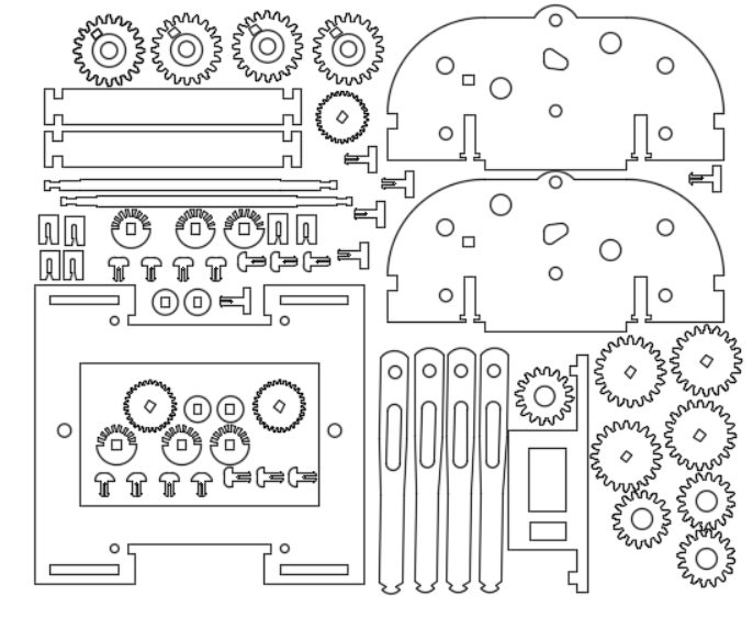
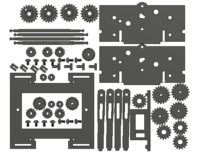
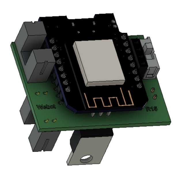
Now that I belong to the Fox.build makerspace I have access to a laser cutter which makes very reproducible cuts. My initial goal was to make product it with acrylic, some off the shelf hardware and the other electronic bits and bobs from Aliexpress. Now I am thinking about adding a few 3D printed piece if it would significantly improve the performance.
I have worked on it for over 2 years, made over 50 different revisions of the laser program but there was always something not quite finished. I decided to start to publish and rev as I go along. Once it looks solid, I can put it on Tindie and make that $1 I have in my yearly goals. I have bought the hardware to support a Tindie run of 50 pcs many times so I have boxes of hardware in the basement.


 zapwizard
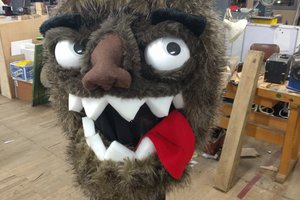
 Kevin Harrington
 Mark Langford
 Alex Rich
Very cool project! Looking forward to future developments.
I saw in the video that Tortellini could pivot left while at a standstill, but can it also make a turn while walking forward? That's one of the main issues I'm wrestling with in my own project.
Would love to see some more info on the leg movement scheme you're using. And more videos. (No pressure though, just a suggestion.)