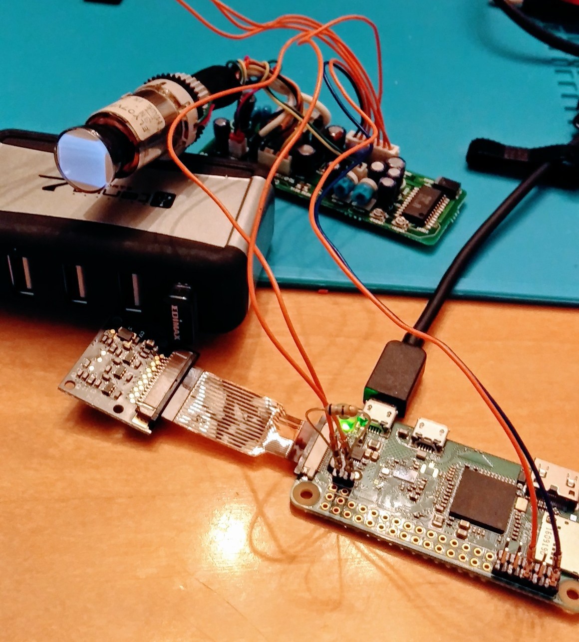
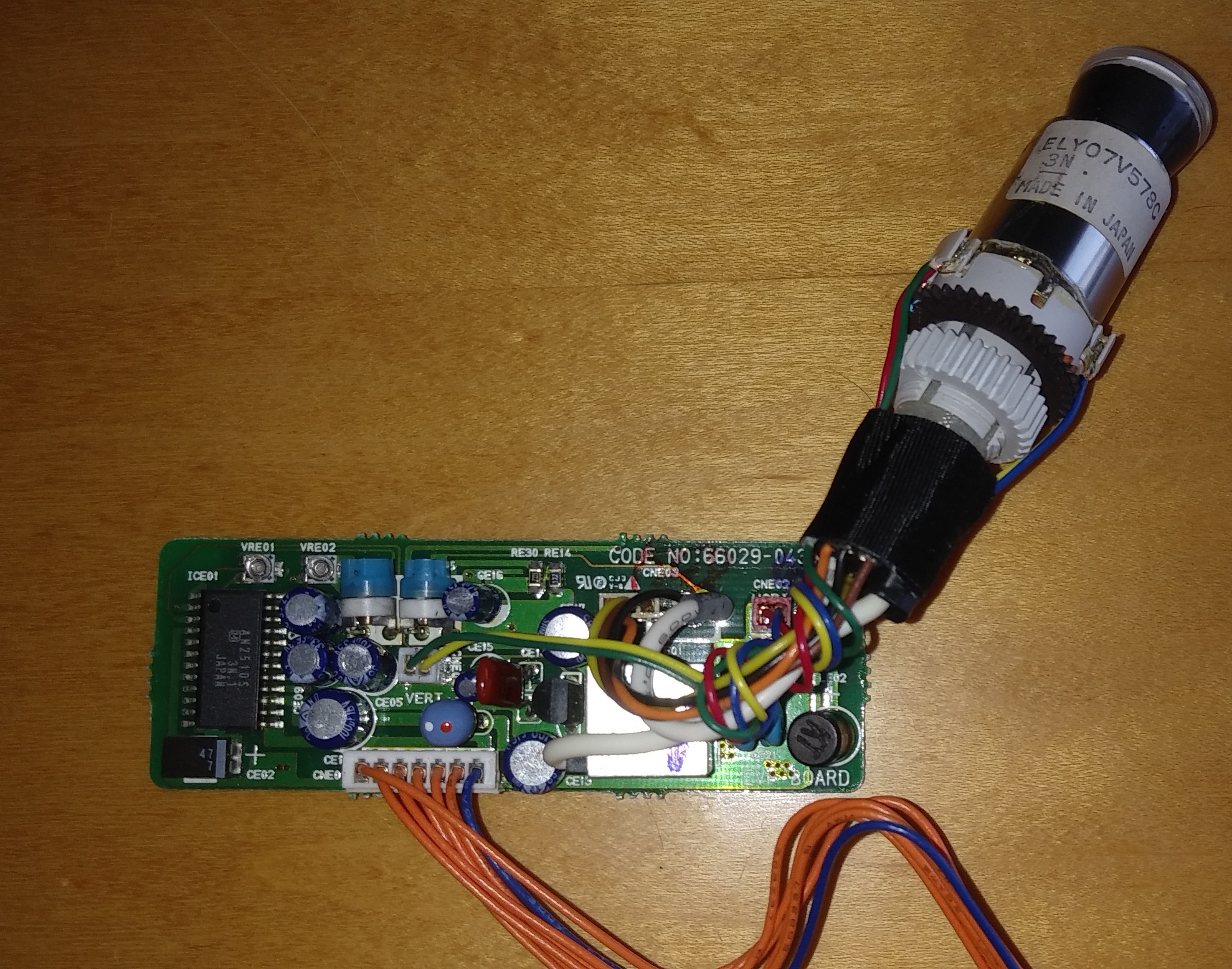
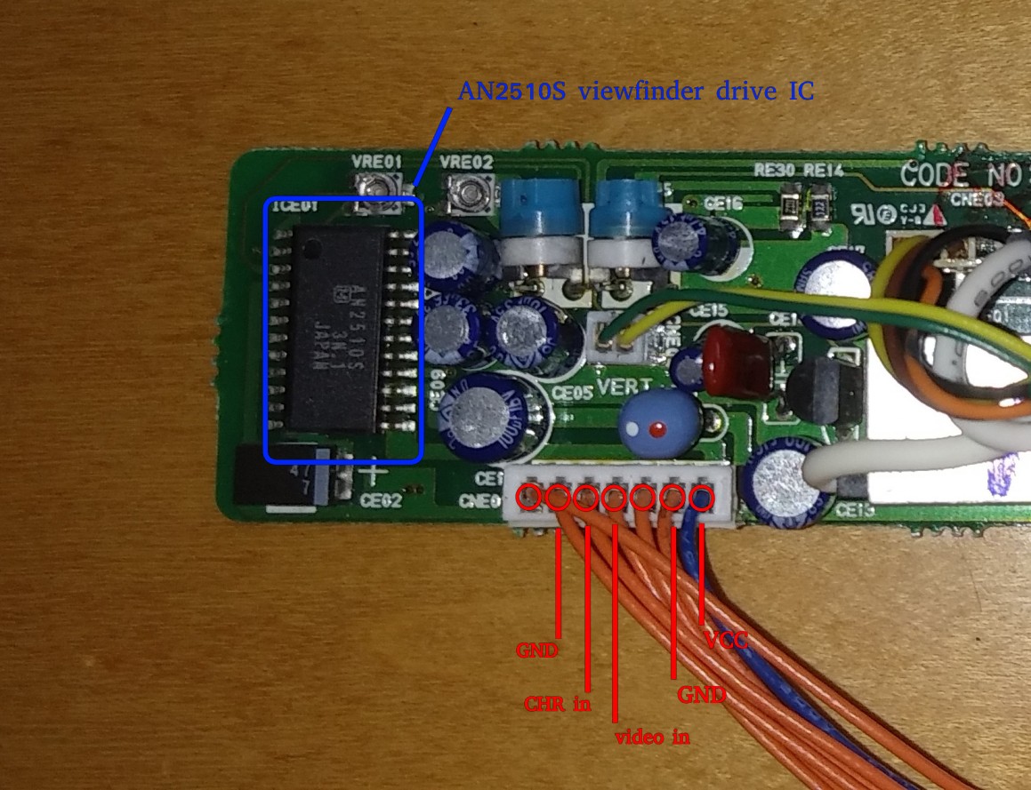
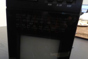
• Troubleshooting and roadblock

    Jeffrey Jacques01/28/2019 at 03:31 0 comments

    So all I'm getting are some flashing scan lines during pi booting. Went through the extra wires alternating pulling them 5V / 3V high or low. Got some bright squiggles on CHR high and another pulled high seems to degauss or reset.  Need to work from a known good so crimped a Dupont connector to an RCA video cable to an input on my TV. We got video, so the Pi is working. Hmmm maybe impedance issue? Plug on the TV reads 75 ohms, 3K ohms on the viewfinder video input... tied video in to ground with 68 ohm resistor (closest I had) a little more squiggly on booting. Have to wait for an order of 75 ohm resistors to arrive. If that's not it I may be stumped / something is bad.

  • Raspberry pi config

    Jeffrey Jacques01/28/2019 at 03:09 0 comments

    Solder headers on the two contacts labeled TV and any +5V and GND. Attach the Pi NoIR camera using flex cable and power it up.

    $ sudo raspi-config

    Interfacing Options -> Camera -> Enable

    Boot Options -> Desktop / CLI -> Console Autologin

    $ sudo vi /boot/config.txt

    add the following lines

    framebuffer_width=320
    framebuffer_height=240
    sdtv_mode=0
    sdtv_disable_colourburst=1

     $ shutdown -h now

    Power off, crimp Dupont connectors onto wires and plug into appropriate headers. Unplug HDMI.

    Power on and the CRT glows.

    No Dmesg output From Linux. Time to troubleshoot.

  • Investigation

    Jeffrey Jacques01/17/2019 at 18:44 0 comments

    First we will need to investigate the electronic viewfinder daughter board taken from a '90s GE VHS camcorder.

    This board was connected to the main board with a 7 pin cable so presumably all the video and control signals and supply voltage are carried through this cable labeled CNE01 but we don't know the pinout or voltages. Since these viewfinders are usually controlled by a dedicated IC the best course of action is to read off the number on the part labeled ICE01 and find a datasheet online. A quick google search finds a dusty pdf for AN2510S Video Camera Electronic Viewfinder Drive Circuit. Looks like a match.

    Let's take a look at the ratings and pinout of this IC:

    So it looks like our max voltage is 5.3V, typical is 4.8V and the test circuit max draw is 34 mA.  Not bad, should be able to run this off a normal USB power brick. The next step is to take a continuity tester and trace the leads on the chip to the pins on socket CNE01. This lets us match the datasheet pin functions to those directly connected to the cable but we're still missing some, most importantly (18) video input.

    Maybe the example circuit diagram can help:

    Ok the example has a .22μF capacitor on pin 18. Let's set our multimeter to capacitance mode and see what we can find. Between pin 18 on the IC and pin 4 of the cable socket reads .20μF. Close enough, that must be our video in.

    Here's what we got so far:

    CNE01AN2510S (ICE01)Function
    12 VCC (2)
    12 VCC (1)
    VCC+ 5V
    28 GND (1)GND
    3??
    418Video Input
    516 CHR InputCharacter Overlay 3V
    64 GND (2)GND
    7??

    Pins 3 & 7 are a mystery for now. Most likely control signals of some sort.