 Hulk
HulkStep 1: Hardware Requirement - 1

For this project, we need a mixture of both electronic components and woodworking tools.
- The electronic components include:
- A Perfboard
- NodeMCU
- 220v AC to 5v DC Buck Step-Down Module
- A Buzzer Shield or a Buzzer and a 100Ω Resistor
- SPDT switch
- 4 x TM1637 4 Bits Digital 7-Segment Displays
- Couple of coloured LEDs and equal amount of 220Ω Resistors
- Few connecting cables
- A USB cable to upload the code
- and General Soldering Equipments
Step 2: Hardware Requirement - 2

For the workworking bit we need:
- Palate Wood
- Pencil
- Measuring Tape
- Hand/Chop Saw
- Hammer
- Nails
- Sanding Tool
- and Personal Protective Equipments (PPE) for woodcutting
I am making the enclosure out of pallet-wood as I have a massive pile of pallets left over from my other DIY WoodWorking Projects. You can also make the box out of cardboard or plastic container and paint it to give it COOL look.
Step 3: Topic Covered

Step 4: The Plan

The plan is to make a 24cm x 10cm box to hold the circuitry in it.
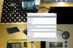
When the device is powered on, it will first connect to the specified Wi-Fi network using the SSID and password pair provided in the code. Once a connection is made the code uses a combination of the "Google API key" (I will show you how to generate it in the later section) and your "YouTube Channels’ ID" to fetch the data from the YouTube server. The device then displays the view and subscribers count using the 7segment display.
After displaying the information it waits for 5 minutes before fetching the next set of information from the YouTube server. A variable is used to store the current subscriber count. If the new subscriber count is greater than the old count the buzzer goes on and the blue and white LEDs flash (glows) alternatively.
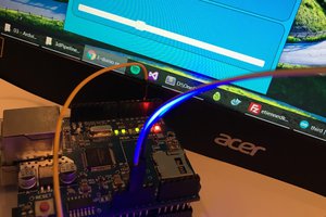
Step 5: Wiring

The wiring is very simple. We will start by connecting the 7-Segment displays to the microcontroller. Each of these displays have 4 pins, 2 for power and one for clock and the other one for data. Connect the data and clock pins to NodeMCU as per the instruction provided on screen.
Then we will connect all the VCC pins of the displays to the 3.3V pin of NodeMCU. Next, connect the buzzer shield/buzzer with the 100Ω Resistor to the D8 pin. After that connect the blue and white LEDs to D9 and D10 pins with a 220Ω current limiting resistor respectively.
Now, go ahead and link up all the ground pins to the GND pin of NodeMCU. Once all the pins are connected, connect the switch to the VIN of NodeMCU and GND to GND of the stepdown converter.
Attachments

Step 6: Libraries Used


The channel's user and channel IDs are listed under "Account information"
Sign in to your YouTube account.
In the top right, click your account icon > Settings.
From left hand panel click on "Advanced settings".
Here is the list of libraries that we need for this project.
> Software Libraries:
- TM1637 LED Driver: https://github.com/avishorp/TM1637
- ESP8266WiFi: https://github.com/esp8266/Arduino/tree/master/li...
- Arduino Json: https://github.com/bblanchon/ArduinoJson
- Arduino YouTube API: https://github.com/witnessmenow/arduino-youtube-a...
You can download them all from GitHub, I have provided the links in the description below. Once downloaded unzip and rename the libraries by removing any special characters and the "master" from their names. Place the folder in your Arduino's libraries folder. You may need to create the Libraries folder if this is your very 1st library. Restart the IDE so that it properly loads the KEYWORD file, Examples, and adds the Library to the Library Menu.
> Unique Identifiers:
- WiFi SSID/password
- YouTube channel ID: https://support.google.com/youtube/answer/3250431...
- Google API Key: https://cloud.google.com/docs/authentication/api-...
- Along with the libraries you also need few unique identifiers for this project.
- The first one is the SSID and password of your wireless network.
- Then, you need your YouTube...
 SUF
SUF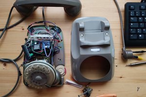
 Giulio Pons