 Peter Lehnér
This is a prototype !
I am already working on prototype 3 so i won't put more time into this one.
But by request i uploaded the current prototype to thingiverse all files ar located there :-)
And remember its not a polished finished project..
First watch my youtube video about it.
Current status:
It works and can count from 0-9 when turning the gears.
But its is still a prototype and not elegant yet, i want to reduce complexity more and reduce friction. I have a lot of ideas in my head but hard to find time to do make them..
I am working on 10 position indexing gears so that one turn of the input changes display one number. See included file for my current idea regarding that: test_10_pos_index.stl
The reason i did this was the following:
Big led displays draws a lot of power and can be poorly visible in daylight.
The mechanical displays that exist today have one electromagnet for each segment, that requires a lot of wires and electronics.
This display can be used without any electronics att all, for goal keeping, clocks, etc.
And of course i wanted it to be as much 3D printed as possible.
My goal is that when it is finished, multiple display segment will be serially connectable so that if you connect 3 units they will be able to count to 999. That's when one segment switches from 9 to 0 it also switch the display connected to it +1 and so on all mechanically..
The main use of a display like this is that it can be run all mechanical, for goals/points keeping, mechanical clocks, counters, etc where no electronics at all is needed.
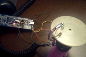
To make it electronic just a $2 stepper and driver is needed to drive multiple segments..
Like this one: 28BYJ-48 stepper motor and ULN2003 driver, witch make it very easy to control from a arduino and other controllers.
Great for temperature display and youtube subscription counters and so on, only draws power when switching numbers.


 kevarek
 AIRPOCKET
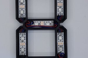
 Fabian
After being inspired by your project, it took me year and a half, but I finally got a working display: https://hackaday.io/project/173798-mechanical-7-segment-display
I haven’t been able to get it as compact as yours though.
Thanks for posting your project, it is a really great one that inspired me to learn about designing mechanisms.