Project Goal |
Determine the constraints to be able to observe (measure) the Hall voltage in a conductor. We would like to use a PCB as a prototype Hall element. Specific constraints to determine are:
- Magnetic field limitations; how big can we go??? (constrained by $$$)
- Electric current limitations
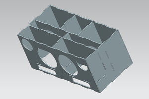
- Dimensions of hall element; in this case I would like to use a thin conductor, like PCB or metal tape (dimensions constrained by 2)
- Instrumentation & Error Budget (what levels of hall voltage can be attained, how do we plan to measure the hall voltage, and do it somewhat accurately?)
Once we figure out the above, we'll get the materials and test.
Hall Voltage TL;DR |
VH = -(1 ⁄ nq) * I * B ⁄ t
The 3 factors which influence Hall voltage magnitude:
- The longitudinal current in a material (conductor or semi-conductor).
- The magnetic field component cutting through the material, perpendicular to the direction of current
- The material itself where (1 / nq) is known as the Hall coefficient for conductors and t is the thickness
Note: The Hall coefficient (1 / nq from above) becomes a bit more complex when you start using materials that have more than one type of charge carrier (e.g. semi-conductors). However, the concept is the same.
Design of Experiment |
Now to the fun part: if we are intending to see what magnitude of current and magnetic field we will need to measure Hall voltage, we know we can't apply an infinite amount of either...we obviously have some constraints :).
Coming Soon
Background Info |
What Is the Hall Effect? |
The hall effect is the phenomena of a voltage (known as Hall voltage) formed due to the presence of:
- current flowing in a material
- magnetic field which is perpendicular to the current
where the Hall voltage:
- appears in the plane which is perpendicular to both the current and magnetic fields, and
- whose polarity is determined by the polarity of charge carriers and the directions of both the current and magnetic field.
The Hall Voltage: A Closer Look |
When we talk about electric current, we're talking about moving charges. When these moving charges cut through a perpendicular external magnetic field, a force is exerted upon these charges: the Lorentz force. The same phenomena that accelerates projectiles beyond the speed of sound (aka the Railgun) is the same force responsible for Hall Effect.
Notice how I said "moving" charges above. This means that if I take an otherwise non-magnetic (or weak magnetic) material (say copper), put an electric current through it, then place it in a magnetic field, the moving charges will start responding to the magnetic field. Again, this response depends upon the magnitude of the current (moving charges) and magnetic field (in addition to some material properties). Pretty sweet, right?
Here's the mathematical formula (don't be scared, use the google or the references):
... Read more »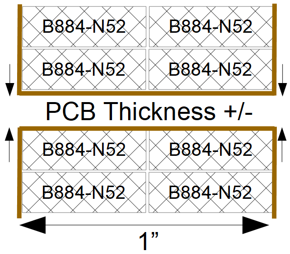
 RoGeorge
 mircemk
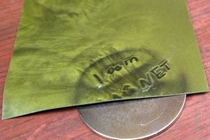
 DeepSOIC