Hello!
3+Pi is nothing conceptually new. This is just as any 3D printer-based board which talks through UART. Except instead of having a USB to UART layer, this is directly using the UART port on the Raspberry Pi.
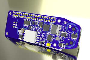
Designed specifically to act as a Raspberry Pi Hat. 3+Pi conceptually means, 3 Axis or more (thus the +) and mounted onto the Pi… as a hat. (umm... Thus the +Pi again.)
With an ARM Cortex M4 STM32F302CBT6, the 3+Pi will be able to handle all the low-level logic and real-time aspects of driving the motors for whatever purpose you might want... Hopefully. Using the TMC2041's ‘dual in one package’ stepper drivers, communicating with the STM through SPI, the option to add 6 Degrees of Freedom will not be an issue... Unless you're driving the stepper coils hard then yeaaaahhhh… probably not a good idea ☹
Optional CAN controller will let you use the 3+Pi for any CAN-able devices in the bus allowing you to directly talk to the STM for stepper feedback and monitoring or stepper driving. With the optional feature to talk to the Pi and ask it nice questions like ‘how is the temperature going?’ and ‘how much resources are you drawing?’ ‘how are you feeling?’ It's good to talk... especially for this hardworking board.
Finally, with the whole doctrine of USB-C motivation, I have succumbed and made the board support USB-C 100W full usage. I mean, it will be able to negotiate a whopping 20V 5A if the supply grants it but will be able to be programmed to drop the power draw should there be an issue. If there isn't any 20V or high current supply the board will work functionally with a normal 5V 3A supply, which will only power the Pi, then prompt the user about low power input - thus putting the STM32 to deep sleep until next power up, hoping that the power supply is enough juice both up.
So where can this be used? Possibly for 3D Printers, CNC machines, laser cutters or virtually any low power demanding 6DoF applications. I have so many outlandish plans for this project such as adding the potential to respond to physical motion feedback on said 6DoF to have a good closed loop control system. I hope this inspires you to design your own crazy project (please feel free to let me know about it and I'll try to support you with my skills as much as I possibly can.)
This is a rapid prototype for now, so it's been designed quickly and will likely have some bugs/hiccups here and there. I’ve been working on this after my usual day time job, so... I'd say there isn't much time put into this yet. Regardless, I intend to do it no matter how long it takes because of I love doing such projects.
Thanks for reading...
/..\
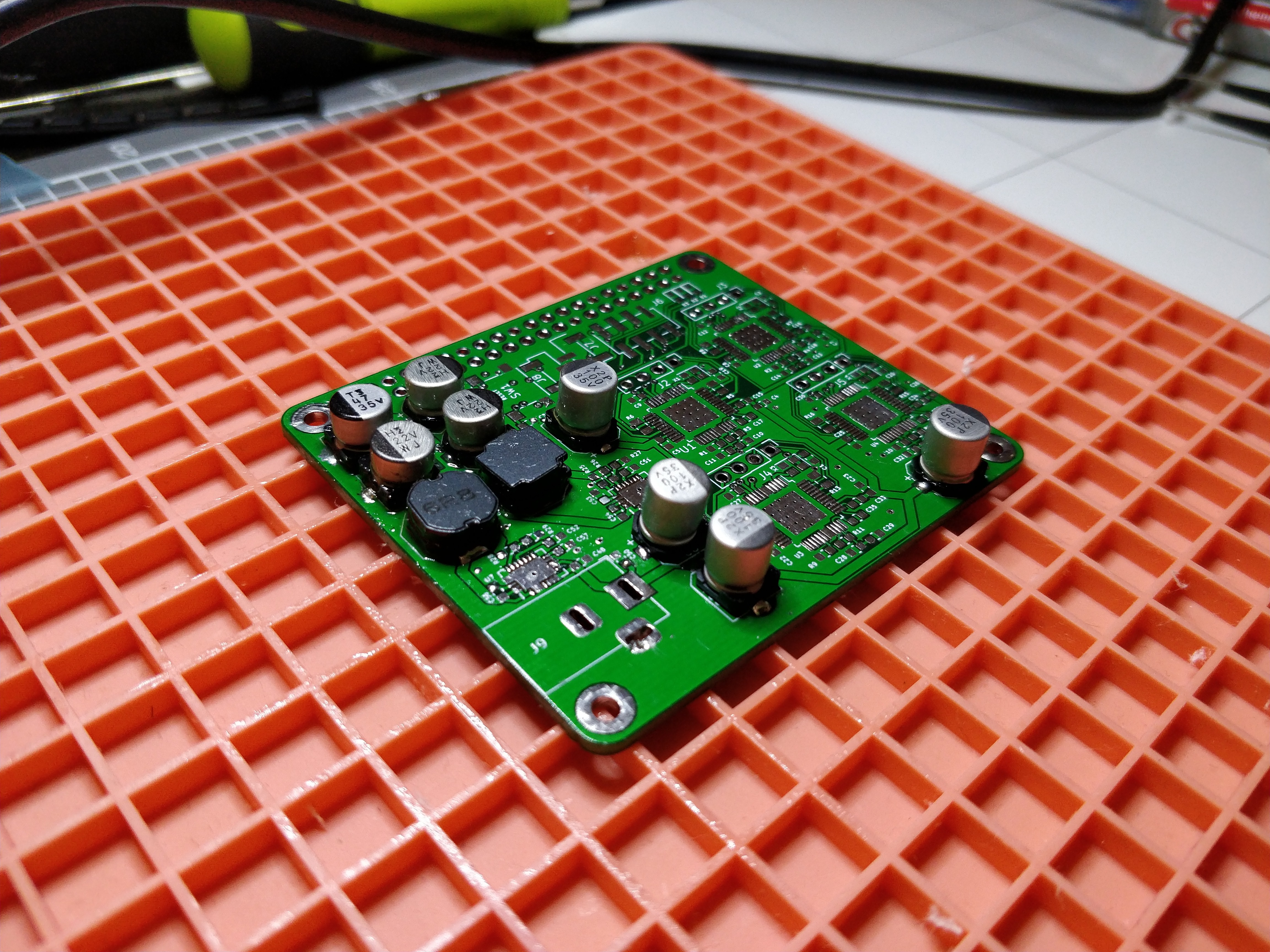
Here is the extract of the original board - I think it's important to show improvements/non-improvements of a project through archiving and less deletion.
{ The board consists of:
- The Cortex M4 STM32F401RE chip mostly handling the grunt of the lower-level tasks needed to create the signals for the 4x TMC2100 stepper driver modules.
- A bunch of bulk Aluminium caps to smooth out the power supplied and be rated to handle 24V input. This will reduce the need for thicker current power supplies rated at 12V. [Edit: 18-02-2019 This was the original idea with Prototype V1.0-1.2p]
My power target is to go lower than 96W total... For now. [Edit: 18-02-2019 This was the original idea with Prototype V1.0-1.2p] }
 Tobius


 Teemu Hakala

 julien
Keep in mind that for 3D printers or CNC's, you also need various I/O's for:
- 3 or 6 or more digital inputs for limit switches, surface probe
- 3 or more digital outputs for switching heaters, fans, motors, lasers on/off
- 2 or more analog inputs for temperature feedback
- 1 or more pwm outputs for optional servos (to position probes, for example)
- tx/rx for locally-attached control panel (smart lcd/touchscreen)
Folks may overlook your board if it doesn't have these features.