 Bud Bennett
Please forgive me. It's been nearly 4 years since I worked on this problem. A lot of the details have probably been forgotten in the interval. There is a lot of ground to cover, so this might be a very long log entry.
Initially I thought that the way forward was to use a velocity sensor. But subsequent investigation led me to conclude that a displacement sensor was best. I somehow stumbled upon an article by Dr. Randall D. Peters, a professor of Seismology at Mercer University at the time. I lost the original article, but Dr. Peters has written extensively on the subject of using capacitive displacement sensors to detect movement of seismometers, and even patented (U.S. Patent # 5,461,319, Oct. 24, 1995) the concept of a differential capacitance transducer. I will make the patent available in the files section of this project.
The Concept:
Dr. Peter's basic approach was to create a capacitive displacement sensor that was inherently non-contact (therefore no friction), highly linear, differential, and very sensitive. This is a figure from a Dr. Peters paper describing the sensor.
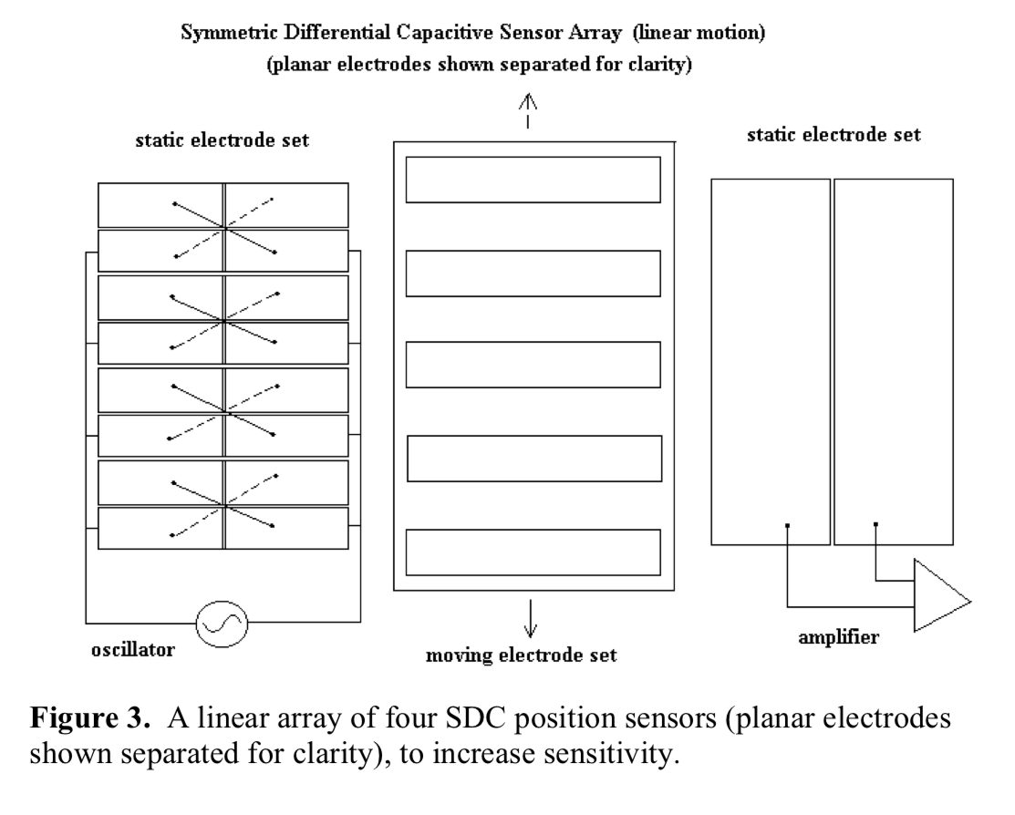
The sensor consist of three plates, which are superimposed on one another: the exciter plate (at the left), the rotor plate (middle) which moves, and the capacitor plate (right). The figure above refers to "linear motion" to simplify the concept. In our case the motion is rotational -- an easy translation.
So what you have here is an exciter plate where the stimulus is applied, a rotor plate that "blocks" the excitation, and a capacitor (static) plate that measures the result via differential means (an amplifier, in this case.) Displacement is measured when the rotor plate moves - it changes the capacitance measured between the excitation (a stator plate) and the capacitance (a stator plate) when the rotor plate changes position.
The rotor plate blocks the signal from the exciter plate to the capacitor plate wherever there is metal. If the rotor is positioned so that it exposes the exciter plates evenly, then the effective capacitance of the sensor is zero. If the rotor plate moves up or down even the slightest amount then the exposed plates of the exciter are unbalanced and the capacitance changes in direct proportion to the movement. Note that the exciter electrode set consists of cross-coupled plates. This arrangement provides for zero displacement when the stator is aligned with the stators, but when the rotor moves it makes the capacitance change (positive or negative) in direct proportion to the displacement.
The Implementation:
Unfortunately, the boom is fixed at one end so the displacement is rotational in nature. Fortunately, Dr. Peters provided some answers. He was selling a seismometer that employed two pendulums, x and y, called the Volksmeter, for about $1500. The users manual for the Volksmeter contained a lot of information.

He is giving it all away at this point. I was able to design the two stator plates and the rotor plates from all of the information that he had given away. The patent was granted in 1995. Normal patent life is 20 years, so it has expired as of this writing. Note the disclosure of the AD7745 chip.
My Design:
The AD7745 is a differential 24-bit capacitance-to-digital converter. It has a maximum differential capacitance capability of about 4pF. It is desired to create a capacitor that will generate nearly ± 4pF for a full scale movement.
So what is a full scale movement? I arbitrarily chose this to be ±5mm. We don't get a lot of seismic activity here in Colorado. There is no need to be able to respond to large displacements. A ±5mm ranges is huge compared to expected incidents. The 5mm range also must include drifting of the mechanical system over time and environmental conditions (temperature, humidity, etc.) The 5mm range sets the width of the capacitor at 10mm.
Next I chose the distance between the rotor and the stator plates to be a small, but doable 1mm. Now the only parameter remaining is the length of the capacitor. I used the spreadsheet below for that. The spreadsheet assumes rectangular geometries to simplify the calculations. Once I got the spreadsheet set up, all that remained was to pick the length and number of capacitors in the array. I chose N=4 to simplify the design (because my initial attempt was using homemade plates.)
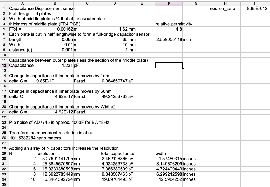
The spreadsheet also allowed me to predict the sensitivity of the sensor. The AD7745 published its peak-to-peak noise level, which forms the floor of the response.
Conversion to Rotation:
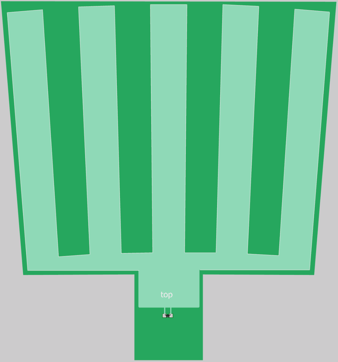
To convert the design from a linear movement to a rotational movement I had to pick a distance from the hinge to the bottom of the sensor. The current mechanical design set this at 16.5 inches. The length of the sensor was set at 65mm, from the above spreadsheet. Now each slice of plate metal is a wedge that is 63.5mm(2.5") long and 10mm wide at the top. This is the exciter plate.
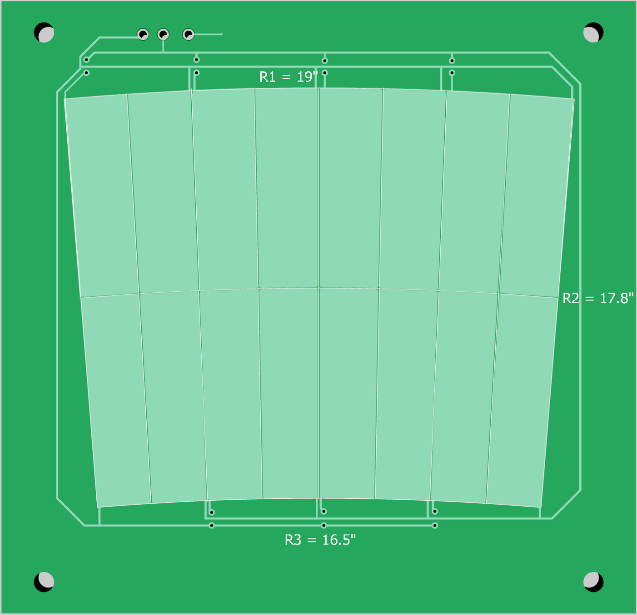
Below is the capacitor plate.
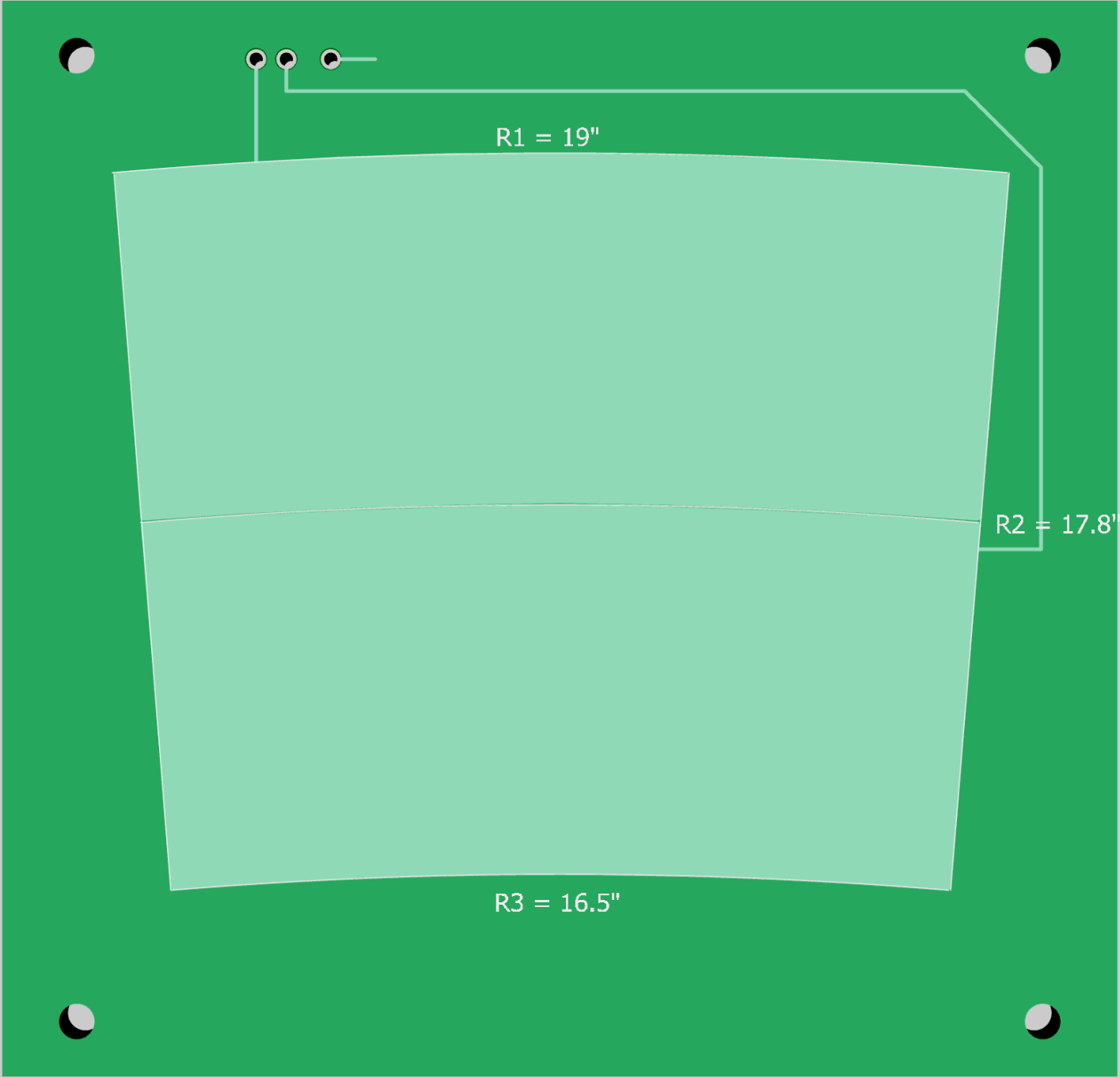
The two stator plates face each other. The radius R3 at the bottom of the sensor is set by the hinge to sensor distance (16.5"). The radius R1 simply adds 63.5mm to R3 to get the desired sensor capacitance. R2 not the midpoint between R1 and R3. R2 must be set to equalize the areas between the upper and lower plates due to the difference in the inner and outer radii. Therefore:
The rotor plate has vanes to block areas between the stator plates but the vanes begin and end outside the stator plate areas -- allowing the stator blades to define the capacitor area.
 I found a PCB foundry in China that only charges $2-5 for 10 boards if they are less than 100mm per side. These boards are just under that limit so I was able to purchase 3 sets of 10 PCBs for around $12, which is a stupendous deal!
Discussions
Become a Hackaday.io Member
Create an account to leave a comment. Already have an account? Log In.
Your work is very impressive and complete.
Would it be possible to put the spreadsheet code in the files? I would like to build the sensor but with to suit another project.
Are you sure? yes | no