 Pero
PeroThe HiFi Amplifier consists of three stages: input stage, voltage amplifier and power stage.
Input stage
Input stage is a differential pair of Q1 and Q5. The pair balanced through the current mirror made of Q2 and Q4 and degeneration resistors R1, R2, R5, and R6. The current of 0.65/150 = 4.5mA is provided by the current sink Q3. Since differential branches split the current equally, there is 2.25 mA on each branch. It means that transconductance of the differential pair transistor is gm = Ic/UT = 2.25mA/25mV = 90 mS.
Voltage amplifier stage
The VA stage is a classical Darlington pair with a current limiter through Q7 set to 0.65/47 = 13.8 mA. The current is supplied by the current source Q9 and is set to 0.65/100 = 6.5 mA.
The VA stage contains a double pole compensation through RC network of C7, C9, and R13. The role of the VA stage is to convert the current from the input stage into the voltage output that will be seen by the load. Therefore total voltage gain is input transconductance times Darlington transimpedance. And Darlington transimpedance is, err, something really high. Open loop voltage gain is actually very high and hard to straight forward calculate but luckily not that decisive. The overall gain is determined by the feedback loop, anyway (later in this post).
Output power stage
Output power stage is basic Class B amplifier made of high-power transistors Q16 and Q17. These transistors are pre-driven by lower power Q14 and Q15. Combined, they form something called Sziklai pair, that improves current gain of the output stage.
Power transistors are biased by collector follower Q10, R18, R19, R21, and RV1. Q10 has to be mounted on the heatsink together with power transistors to ensure thermal tracking. What? When the high power transistors warm up, their dynamic properties will change (i.e. output current). Bias must be able to follow this change, and not them slip out of control. So, when output current start increasing because of silicon warming up, Vce of bias will start dropping and reduce this current. This keeps transistors in the safe operating area.
Output current must be monitored and limited by power resistors R33 and R34 and transistors Q12 and Q13. Monitored voltage is scaled by voltage divider R26/R29 (or R27/R30) by factor of 0.3. When the current reaches the value of 0.65/0.22/0.3 = 9.6A, Q12 (or Q13 in negative half-period) shall tie the predriver transistors base to ground and keep the current limited.
R25 - R28 are here to provide something called single slope current limit. What is this? Our maximum allowed power dissipation is 150W, that means product of Vce and Ic must be 150 all the time. In the Ic - Vce diagram, this looks like the 1/x curve (Ic = 150/Vce). We're ignoring the secondary breakdown curve here. Current limit will keep transistor in the rectangular area under the Ilim. If Ilim is 9.6A then the maximum VCE allowed is 15.6 V.
But if VCE get's higher than 15.6, let's say that it climbs to the value of 20V, then max allowed current will be 7.5A, a value that current limiter will easily allow, and lead the transistor into the destruction. To avoid this, a bit of current is always fed to the bases of Q12/Q13 by resistors R25 and R28. This way, even for smaller output currents than 9.6V, the Q12/Q13 will start to shut down.
Rest of the circuit
To match the speaker's impedance, a Zobel network (R35, C12) and air coil inductor L1 was put.
Global feedback is fed from the output to the negative input of the differential pair via network of R10, R11, R12, C6, C8, and D1. In the middle of audio spectrum, C6 is short and C8 is open, what means that feedback gain (or beta) is 330 / (10k+330) = 0.032. Overall gain, determined as 1/beta is therefore 31.3 or 30 dB.
The HiFi Amplifier consists of all discrete, through-hole parts. It's basically...
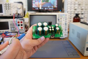
Read more »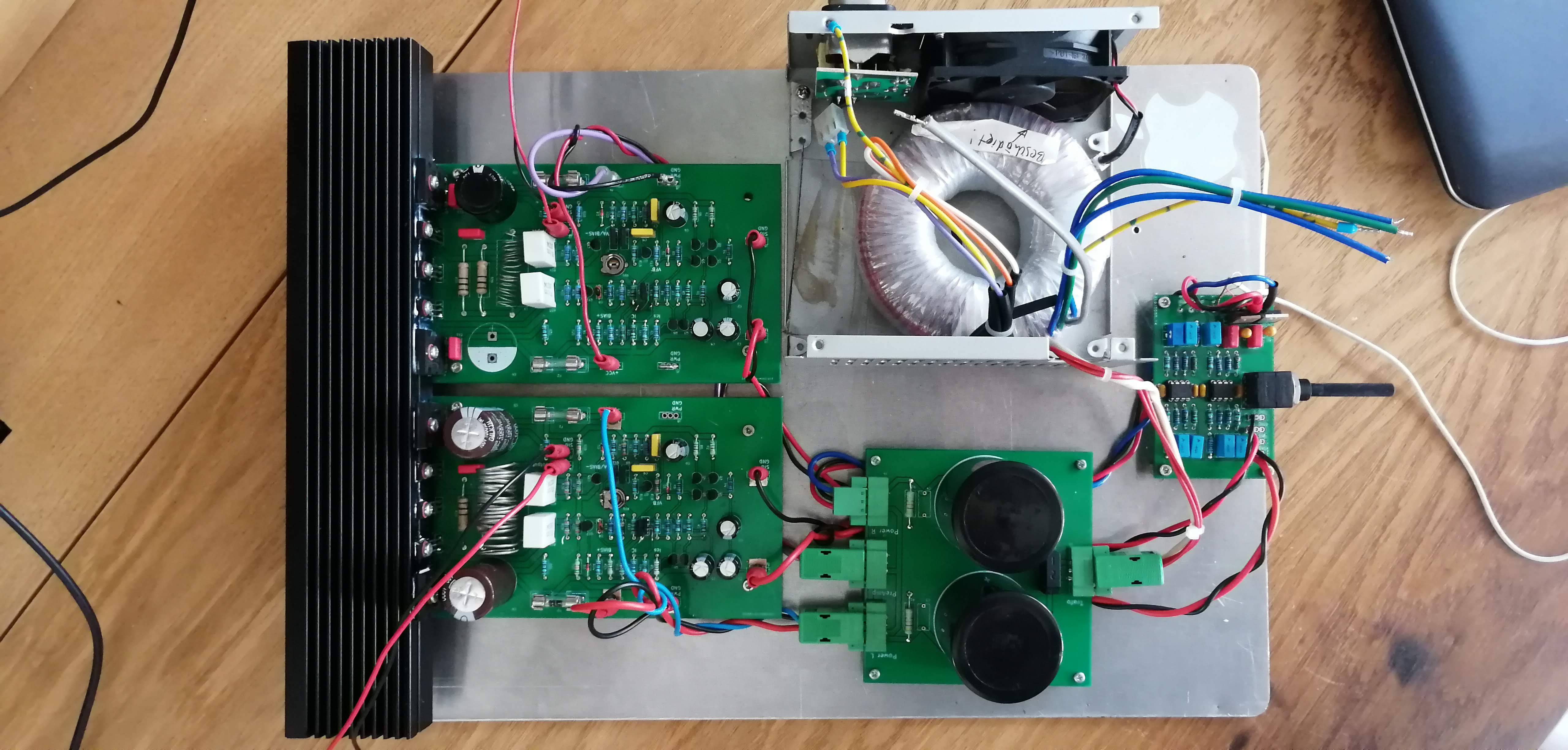 I found a scrap heatsink at the company's dumpster, does the job fairly good.
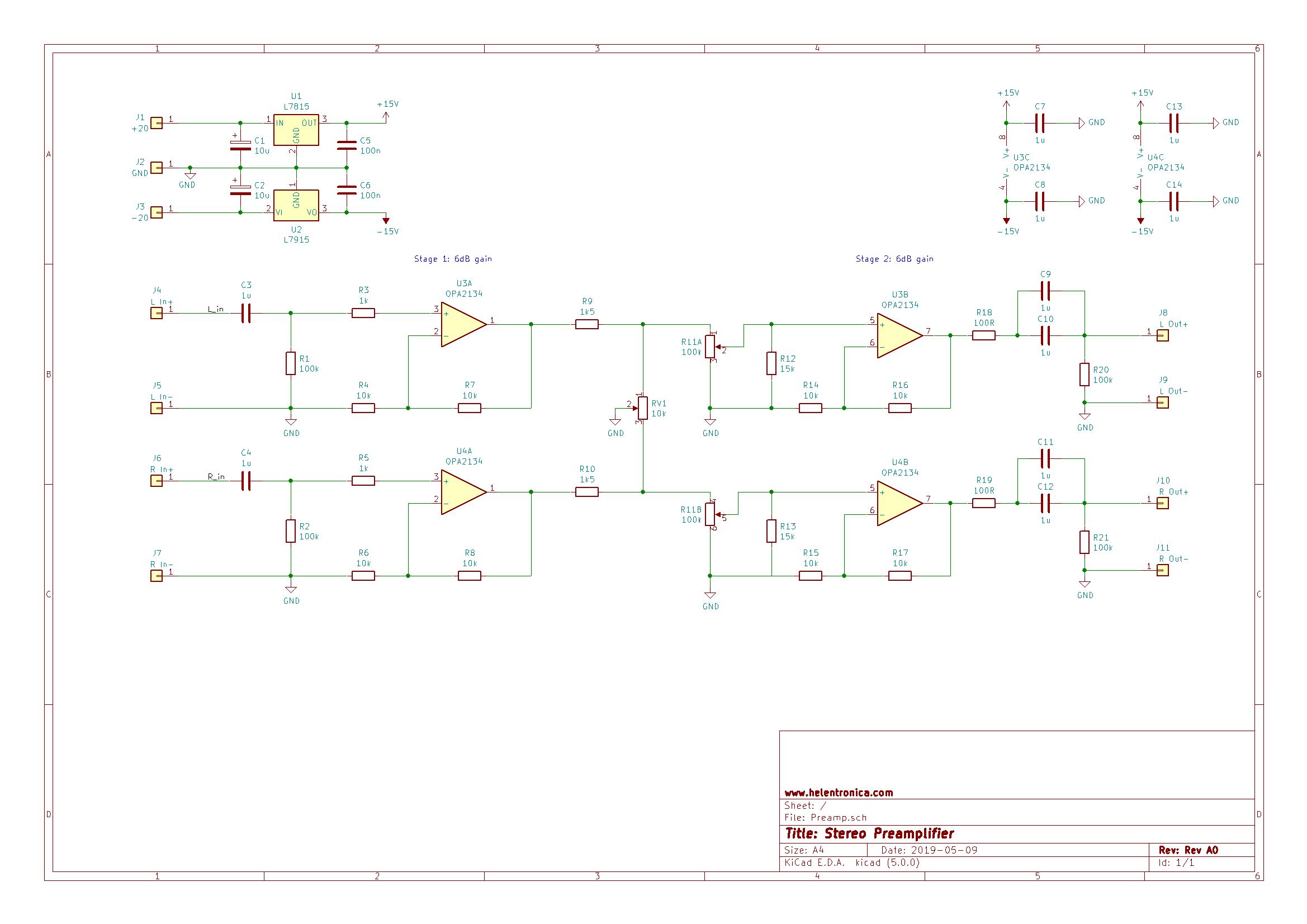
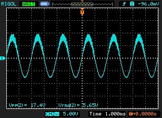 Zoom in on HF glitch:
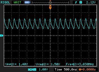


 Jakob Wulfkind
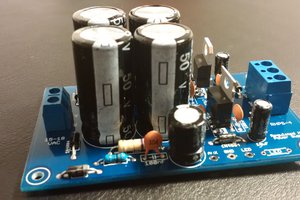
 hesam.moshiri
 Szoftveres
حاجی این مداره واقعا این کیفیتو داره
Is it real? THD = (0.001%).