using THT components for easy soldering and debugging
circle shape
connectors for the wires to be able to taken apart
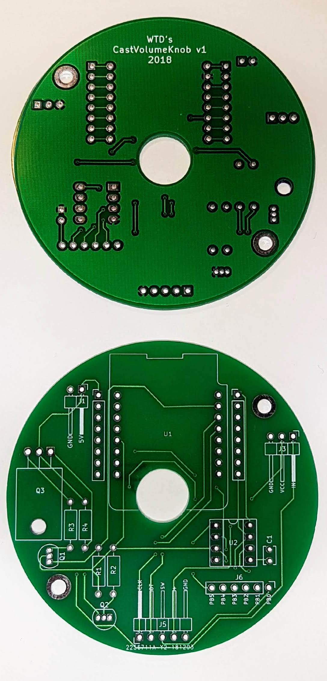
I designed the PCB in KiCAD. Managed to fit all the components on a 70mm circle PCB with a 12mm hole in the middle for wires to run through it. Ordered 10 pieces from JLCPCB and after 2 weeks these showed up.
Not counting a minor mistake in my design - MOSFET legs swapped - It turned out great. After soldering on all the components, everything worked as expected. It was time to design a case for it.
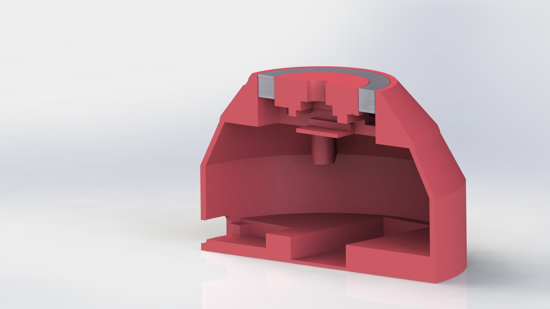
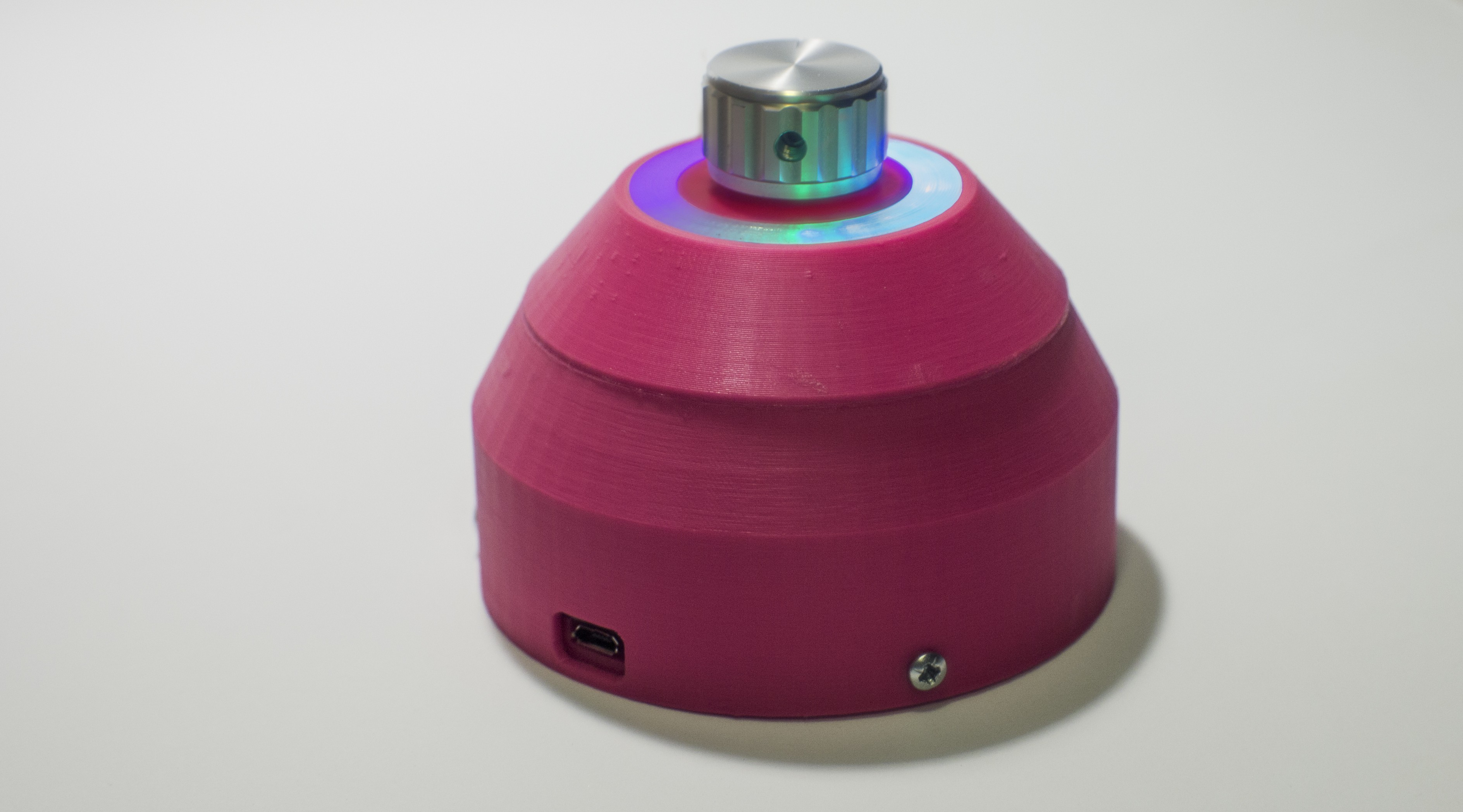
I designed the case for 3D printing in Solidworks. It consist of 5 parts. Only 2 pieces are needed to be glued together, the other parts connects with screws. The whole model can be easily assembled and disassembled.
This is the models Section analysis.
In the top part under the translucent part goes the LED ring. In the top center goes the clickable encoder. in the middle section is the main board. In the bottom is the battery and the charger/boost converter board.
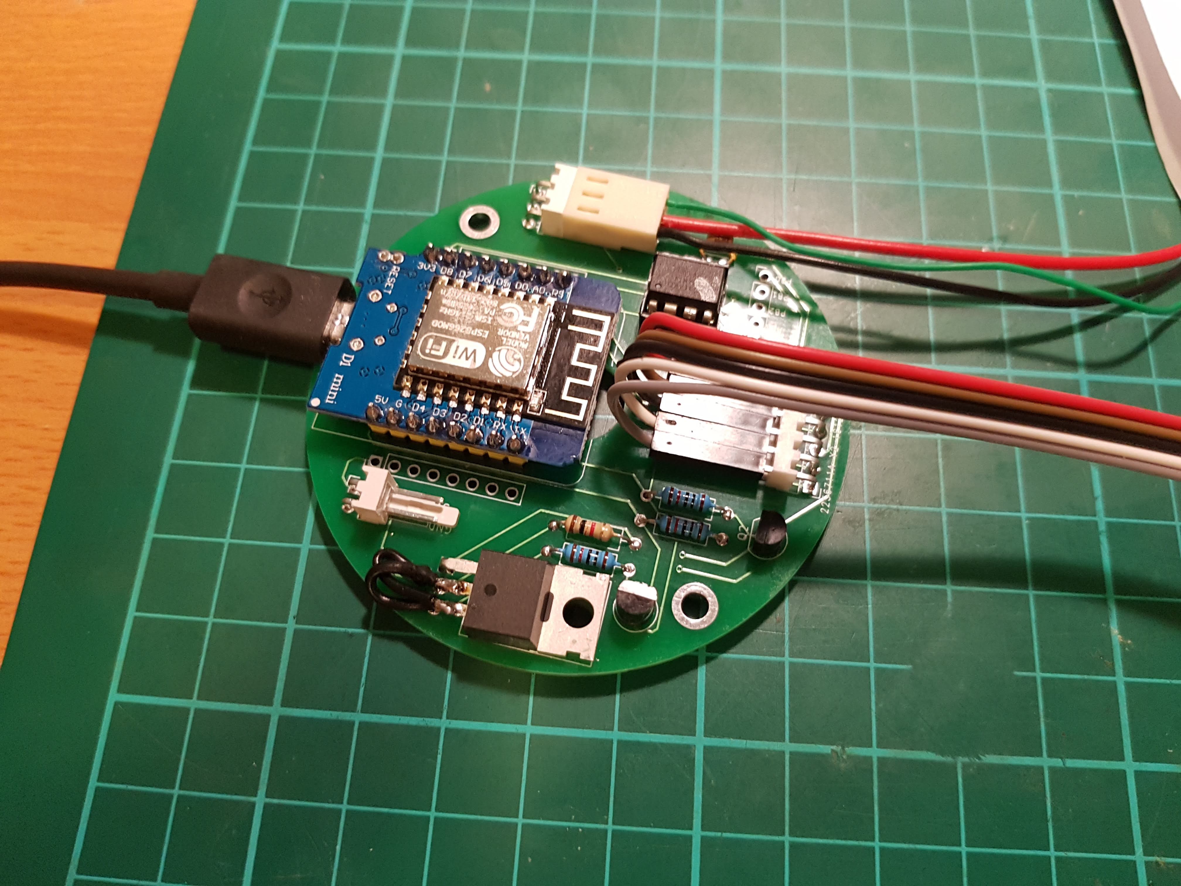
My next step was to implement the hardware and prototype code on the microcontroller.
For the microcontroller I chose the ESP8266 because it's well documented and easy to use wifi capabilities. I wanted to try out micropython for this project. After flashing it into the ESP it was very straight forward to port my prototype code from my PC to the microcontroller. The only third party library I had to use was themicropython-stm-lib/encoder/which I modified to be able to set the initial value of the encoder. To control the Neopixel ring I made a custom class which inherited from the built in Neopixel class.
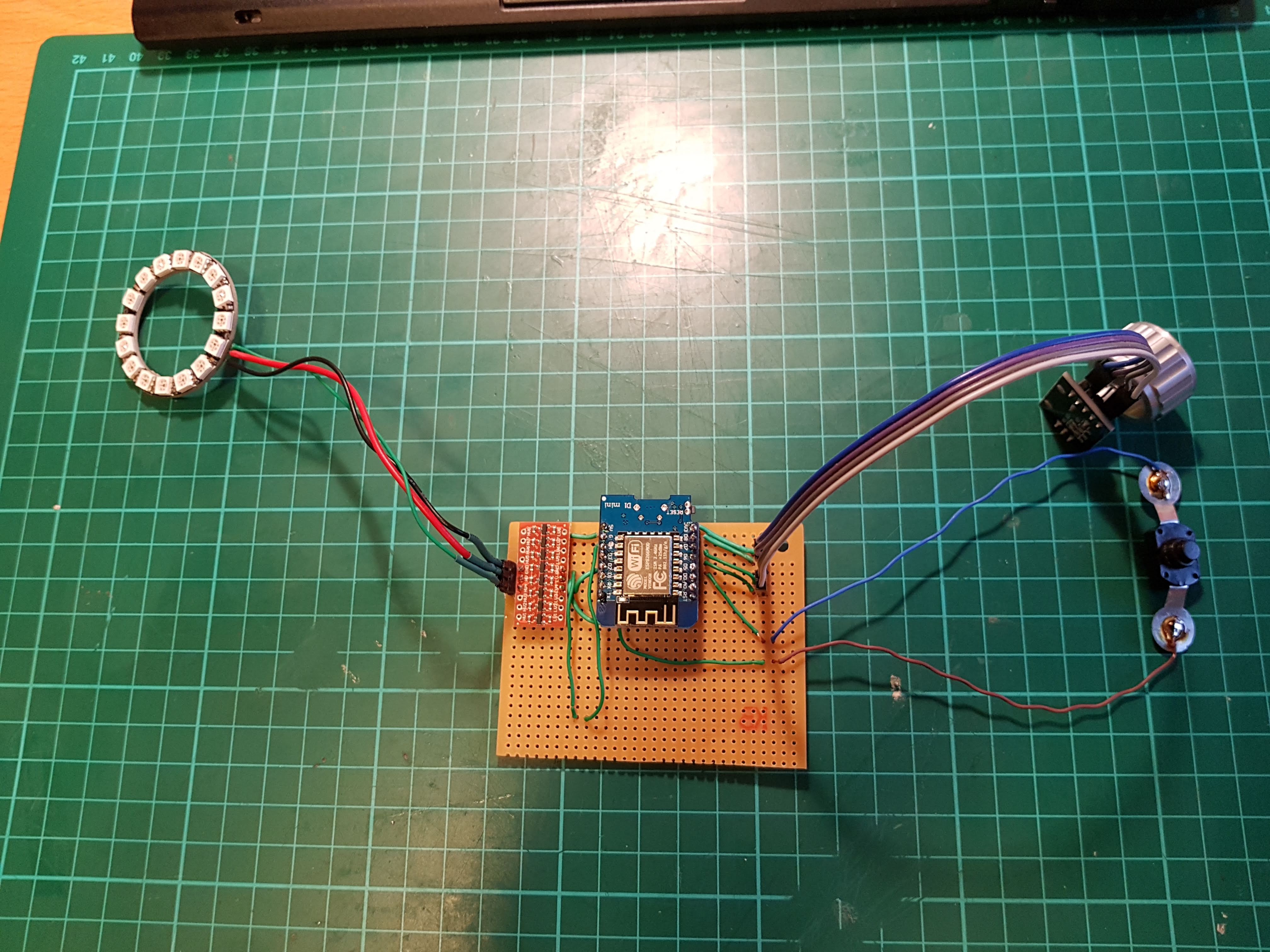
After soldering everything up to a prototype board, it looked like this. Since I wanted to make this project wireless I had to consider the power consumption as well, which was not great at this point. I implemented a MOSFET to turn off the Neopixel ring power when its not in use. The ESP8266 still consumed too much power in standby mode. After a bit research i found out about the ESP8266's DEEPSLEEP mode which is basically turns the microcontroller down completely. To wake it up you need to reset it what is usually done by hooking up the internal watchdog timer to the reset pin, but in my case i only needed to wake up the mcu when the encoder push button is closed. For this purpose I used the ATtiny85 mcu in sleep mode and used interrupts to wake it up. After it wakes up, forwards the next button presses to the ESP to change the chromecast device or stop the playback. With the interrupt handler/watchdog mcu and the MOSFET, the power draw dropped from 100-80 mA to 0.8 mA in standby. According to my calculations, could run for 3 months with a single 18650 Li-Ion battery. This is great! The next thing I was not happy with yet was the visualization. When I was changing the color on the LED ring the brightness was also changing, this was due to the neopixels non linearity. Quick search online I found a gamma correction table for these LEDs, which worked for me reasonably well. At first I divided the LEDs equally to represent the volume level from 0 to 100. Later I realized This was not very useful, because i was hard to tell the precise volume level just by looking at the ring. My solution was to use most of the LEDs to represent volume levels from 10 to 30 percent and to show 0 to 10 and 30 to 100 i used the remaining LEDs on the side. To distinguish between multiple Chromecast devices I assigned a color to each device and used the first LED on the ring to show that color. At this stage I was almost happy with the software functionality, I started to design the PCB.
The first I had to figure out a way I can communicate with Chromecasts. The official API to communicate only supports Android, iOS and Chrome browser. For my purpose either of those options are usable, I needed to communication from a microcontroller.
None of these options were appropriate for my use case but I have found a lot's of useful information in the documentations.
Protocol-buffers:
Chromecasts use a communication protocol called Protocol-buffers or protobuf, developed by Google.
To use protocol-buffers you need to 'define' your protocol in a .proto file which you can compile out to a library. The supported languages are:
C++
C#
Dart
Go
Java
Python
I started development on a PC and I choose Python because it was the easiest and quickest to develop in for me. At first I tried to construct my own protocol-buffer messages but I couldn't get it to work.Then I tried the .proto file and the compiled library from the pychromecast library, but i still didn't got any response.
Then I tried to capture the messages sent from the pychromecast library with wireshark, but the socket is encrypted.
Then I inserted a few print statements in to the library before sending the messages.
With the protocol-buffer libray I could parse these strings and into more readable JSON format.
When i tried to send these back, I got an answer from the Chromecast - Finally!
I continued with this method and found the message responsible for changing the volume, I could even change the value and it still worked.
Done. Right?
Not so fast!
For some reason it only worked when I converted the messages to strings with the precompiled protocol-buffer library.
Due to size and complexity I can't use the protobuf library on a microcontroller, I need a simpler solution.
My first thought was creating messages to set the volume from 0 to 100 and from that create a lookup table. As I was creating that table I noticed a pattern, besides the value of the volume i wanted to change there is a request number. Every message from the initial connection is numbered, starting from 1 and increments by 1. I needed to change that as well. Although almost everything else stayed the same between the messages there was still one important difference. Every part of the message had a number before it indicating its size. Since I wanted to send volume and request values from single digits to triple digits (0 to 100) I needed 5 different sized message. From those 5 created messages I can pick according to the current volume level and request number. And it worked. :)
Now I got it working without any third party library, I was getting closer.
 Ákos Melczer